
Description
DELOMATIC3-CP (DEIF CP‑1 Control Panel for Delomatic‑3 PMS)
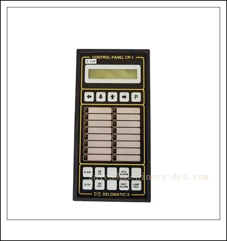
DELOMATIC3-CP
Title
DEIF DELOMATIC3-CP (CP‑1) Operator Control Panel, Delomatic‑3 Marine Power Management System, ARC‑NET Bus HMI for Generator Control & Synchronisation
Technical Specifications
- Catalog Number: DELOMATIC3-CP (CP‑1, P/N: 1044220050D)
- Brand: DEIF A/S (Denmark)
- Product Type: Remote operator HMI / control panel, slave panel for Delomatic‑3 DGU generator controller
- Communication Bus: ARC‑NET token ring, 2.5 Mbit/s, 93 Ω RG‑62 A/U coaxial cable, BNC interface
- Max Panels per DGU: Up to 3 CP‑1 panels connected to one DGU unit
- Supply Voltage: 24 VDC (18–32 VDC operating range)
- Display: Backlit LCD alphanumeric display, dedicated push-buttons and LED status indicators
- Functions: Manual start/stop, synchronisation, load sharing, breaker control, alarm acknowledgement, setpoint adjustment, metering readout
- Environmental: Operating temperature -25 °C ~ +70 °C; humidity 5–95% RH, non‑condensing
- Front Protection: IP40
- Mounting: Panel cutout mounting (control desk / switchboard front)
- Weight: ~4.8 kg
- Lifecycle Status: Legacy marine PMS component, discontinued; spare supply only
- Class Certifications: DNV, LR, ABS, BV, RINA, CCS marine type approval
- Compliance: CE, marine EMC, UL94‑V0 flame retardant housing
Key Features & Advantages
- Dedicated remote operating panel for Delomatic‑3 PMS: Matches DGU generator control unit for marine power management.
- ARC‑NET token‑ring communication: Highly robust deterministic bus, excellent noise immunity for noisy marine switchboard rooms.
- Multi‑station operation: Up to three CP panels can operate the same generator set from different locations (engine control room, bridge, local switchboard).
- Integrated metering, alarm and control: Displays voltage, current, frequency, kW, kVAR, engine parameters and fault alarms locally.
- Manual synchronisation & load control: Enables operator manual closing of generator breakers and load adjustment during commissioning or auto fallback.
- Class society approved: Fully accepted for vessel newbuild and retrofit marine power system installations.
- Simple bus topology: Coaxial ARC‑NET with BNC T-connectors and end termination resistors; fault on one node does not crash the whole ring.
- Long-proven marine platform: Thousands of vessels in service, widely used spare part for Delomatic‑3 retrofits.
Application Fields
- Marine vessel power management systems (cargo ships, offshore support vessels, rigs, tugs, yachts)
- Onboard generator synchronisation, load sharing and blackout recovery control
- Engine control room (ECR) and bridge remote generator operation
- Ship main switchboard PMS operator interface
- Offshore platform auxiliary generator control
- Retrofit and spare replacement for existing Delomatic‑3 DGU installations
- Land-based critical power plants with DEIF Delomatic‑3 power management
Related Product Recommendations
- DGU‑1: Delomatic‑3 single generator control unit (main controller)
- DGU‑2: Delomatic‑3 dual generator control unit
- CM‑2: Communication module, converts ARC‑NET to Modbus RTU for SCADA
- ARC‑NET RG‑62 A/U coaxial cable, BNC tee and terminators
- Delomatic‑3 service and configuration software
- AGC‑4: Modern DEIF generator controller replacement platform
- PPM‑3: DEIF power management upgrade system
- IPM‑1: Delomatic‑3 analogue input measuring module
- OPM‑1: Delomatic‑3 output relay module
- DPD series: Delomatic‑3 protection module
Installation & Maintenance
Installation
- Fit the CP‑1 into a control desk or switchboard panel cutout; secure with mounting clamps and maintain front sealing.
- Use 24 VDC clean, galvanically isolated supply from marine 24 V emergency power; avoid shared supply with heavy inductive loads.
- Wire ARC‑NET bus strictly with RG‑62 A/U 93 Ω coaxial cable and BNC T-pieces; install 93 Ω terminators at the two physical ends of the token ring.
- Keep ARC‑NET bus separated from high-current AC power cables; fit ferrite cores close to each BNC connector to suppress EMI.
- Follow ARC‑NET topology rules: no stubs, no parallel branches, minimum 1.8 m spacing between nodes.
- Assign panel address via internal jumpers before connecting to the DGU; verify bus communication before enabling breaker operation.
- Set alarm limits, synchronisation parameters and load-sharing settings in the DGU controller, not locally on CP‑1.
- Confirm all marine class drawing approvals before commissioning onboard.
Maintenance
- Inspect LCD display, pushbuttons and LED indicators during scheduled vessel surveys; replace worn buttons or damaged overlays.
- Check BNC connectors for corrosion, loose locking and water ingress, especially in humid tropical machinery spaces.
- Verify ARC‑NET communication health; intermittent alarms often come from missing terminators or damaged coaxial cable.
- Keep backup of DGU configuration files; the CP‑1 itself holds no control logic, only operator interface.
- Since this model is discontinued, maintain tested spare CP‑1 for critical vessel PMS.
- Do not open the unit housing on board; internal circuit repair requires bench test environment.
- After replacement, verify all control functions: start/stop, synchroscope display, breaker operation, alarm acknowledge and metering reading.
- Record survey dates, bus resistance checks and panel replacement records for vessel class audit files.

 Send an Email