
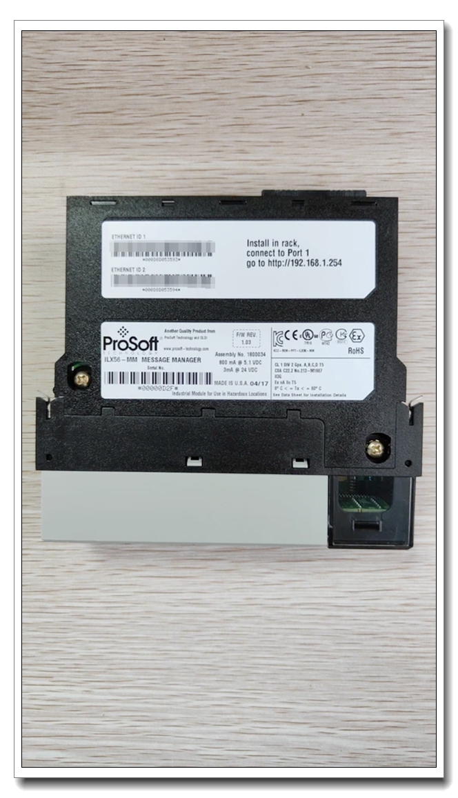
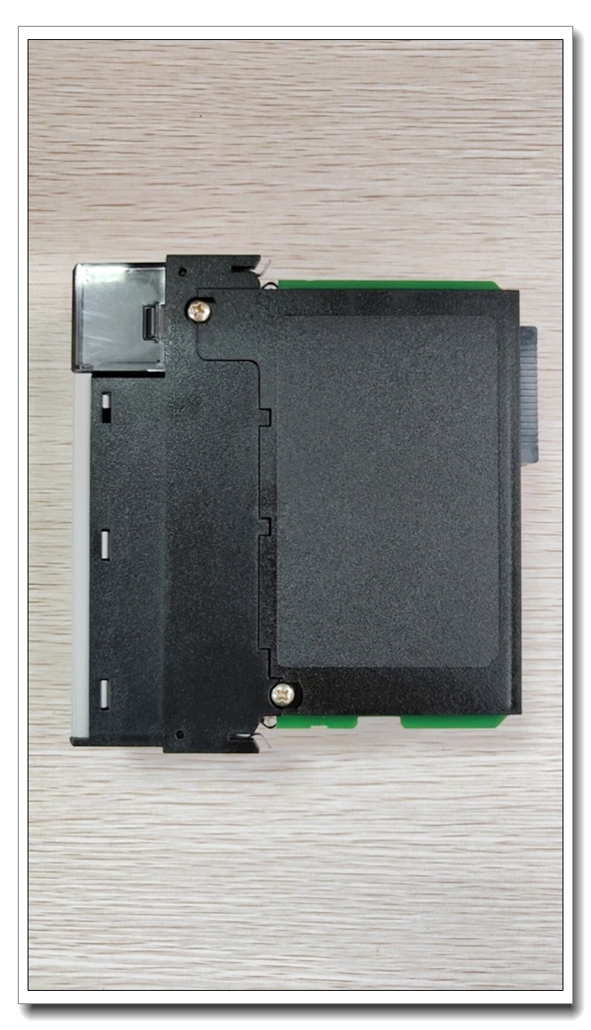
Description
ProSoft ILX56‑MM (inRAx Message Manager Module)
Product Description
The ILX56‑MM is a single‑slot in‑chassis communication gateway module developed by ProSoft Technology for Rockwell Automation ControlLogix 1756 chassis. It acts as a cross‑platform message‑oriented data broker, enabling bidirectional data exchange between ControlLogix PAC and multi‑vendor controllers over Ethernet networks without heavy custom ladder logic programming. It supports Rockwell native protocols, Modbus TCP/IP, and Siemens Industrial Ethernet, bridging automation islands across plant‑floor systems. It features a built‑in web configuration server, 4‑character alphanumeric status display, real‑time clock with lithium‑vanadium‑pentoxide backup battery, and configurable message trigger logic for event‑driven or scheduled data transfers. This module offloads cross‑protocol messaging workload from the ControlLogix CPU, improving controller cycle‑time performance in multi‑system integration projects.
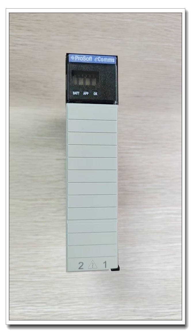
ProSoft ILX56‑MM
Technical Specifications
| Item | Specification |
|---|---|
| Part Number | ILX56‑MM |
| Platform | Rockwell ControlLogix 1756 chassis, single‑slot form factor |
| Backplane Requirement | 1000 mA @ 5 VDC backplane current draw |
| Network Interface | 1×10/100 Mbps auto‑negotiation RJ45 Ethernet, auto‑crossover detectionabb-drive … |
| Supported Protocols | EtherNet/IP, Modbus TCP/IP, Siemens Industrial Ethernet, Rockwell PLC‑5 / SLC / MicroLogix messaging |
| Max Concurrent TCP Connections | 16 client/server sessions |
| Message Memory Mapping | Up to 32768 holding registers for user‑defined data mapping |
| Local Display | 4‑character alpha‑numeric LED status display |
| RTC Backup Battery | Lithium‑vanadium‑pentoxide, rechargeable via chassis power; no routine replacement required |
| Operating Temperature | 0 °C ~ +60 °C (32 °F ~ 140 °F) |
| Storage Temperature | ‑40 °C ~ +80 °C (‑40 °F ~ 176 °F) |
| Humidity | 5 %‑95 % RH, non‑condensing |
| Shock / Vibration | 30 g operational shock; 50 g non‑operational shock; 5 g vibration (10‑150 Hz) |
| Certifications | CE, UL listed, industrial EMC compliance |
| Physical Dimension | 1756 single‑slot footprint; weight approx. 0.40 kg |
| Country of Origin | United States |
| Warranty | 12‑month manufacturer warranty |
Compatibility
3.1 Host Chassis & Controller
- Compatible chassis: 1756‑A4, 1756‑A7, 1756‑A10 ControlLogix local chassis; also supported in 1756 remote chassis over ControlNet / EtherNet/IP backplane connection.
- Controller compatibility: ControlLogix 55xx series; RSLogix 5000 / Studio 5000 software environment. Install ProSoft Add‑On‑Profile (AOP) for full tag‑based configuration; without AOP, use generic 1756 module definition.
- Not supported: CompactLogix local backplane; ILX56‑MM is strictly 1756 chassis‑only module.
3.2 Peer External Devices
- Rockwell: PLC‑5, SLC‑500, MicroLogix, other ControlLogix PAC via EtherNet/IP messaging.
- Third‑party: Modbus TCP servers (drives, meters, RTUs); Siemens S7 Industrial‑Ethernet‑capable controllers; Modbus‑TCP compliant DCS / SCADA hosts.
3.3 Firmware & Software
- Configuration: Built‑in embedded web server (no extra PC software mandatory); ProSoft Configuration Builder (PCB) for offline project editing and download.
- Firmware upgrade: Requires J1 setup‑jumper installed on module rear for firmware write‑enable; remote firmware update available on remote racks with jumper enabled.
Critical Installation Traps & Common Pitfalls
- Backplane Current Overload: ILX56‑MM draws 1000 mA @5 VDC. Calculate total chassis backplane load; insufficient power causes intermittent module drop‑off, communication time‑outs, and RTC clock drift.
- J1 Setup Jumper Mis‑configuration: J1 jumper enables firmware write access. Leave jumper OFF during normal production operation; jumper ON exposes module to unintended firmware overwrite risk. For remote‑rack deployment, jumper may stay ON for convenient remote firmware maintenance with change‑control discipline enforced.
- RTC Battery Pre‑charge: New or long‑term‑stored units require ~20 hours of continuous chassis power to fully charge backup battery. Without pre‑charge, power‑cycle events will lose date‑time RTC values, breaking time‑stamped message logging.
- Network Firewall & Port Blocking: ILX56‑MM uses multiple TCP ports for multi‑protocol messaging. Industrial firewalls must allow required TCP sessions; filtered ports lead to random message failure without obvious hardware fault indication.
- Message Volume Overrun: Maximum 16 concurrent TCP sessions. Excessive configured message transactions produce session exhaustion; implement trigger‑based event messaging instead of unrestricted high‑frequency polling.
- Remote Rack RPI Tuning: When deployed in remote 1756 chassis, insufficient RPI setting causes backplane I/O connection time‑out between module and ControlLogix CPU. Do not use default minimum RPI without performance validation.
- Web‑UI IP Conflict: Factory default DHCP‑enabled; if no DHCP server present, module falls back to static fallback IP. IP address conflict leads to unreachable web configuration page while backplane status LED remains healthy.
- AOP Version Mismatch: Outdated ProSoft Add‑On‑Profile in Studio 5000 results in incomplete tag structure, missing status feedback and download failures. Always match AOP revision to module firmware revision.
Standard Operating Procedure (SOP)
5.1 Pre‑Installation
- Power‑off ControlLogix chassis power supply. Verify total chassis 5 VDC backplane budget can accommodate 1000 mA consumption of ‑MM.
- Inspect module hardware; confirm J1 setup jumper is removed (production default).
- Record module firmware revision, serial number for site documentation.
5.2 Hardware Installation
- Slide ‑MM into an empty single slot on 1756 chassis, lock module latch firmly.
- Apply chassis power; allow minimum 20‑hour continuous power if unit is new or long‑time stored to charge RTC backup battery.
- Observe front‑panel LED and 4‑character display; confirm module passes self‑test and enters idle operational state.
5.3 Network & Software Configuration
- Connect Ethernet cable to ‑MM RJ45 port; resolve IP assignment (DHCP or assign static IP via web fallback address).
- Import corresponding ProSoft AOP into Studio 5000 project; add ‑MM module definition to I/O tree, configure RPI for local or remote rack deployment.
- Open embedded web configuration server via web browser; define peer device connections, message transfer rules, trigger conditions, register mapping tables. Save configuration inside module non‑volatile memory.
- Download ControlLogix project to controller; establish backplane connection between CPU and ‑MM.
5.4 Commissioning & Validation
- Monitor module status tags inside ControlLogix controller; confirm no backplane fault codes.
- Execute manual message test transactions towards each peer controller/device; validate read/write data consistency.
- Verify event‑triggered message execution; check timeout and error status counters for communication failure statistics.
- Perform controlled chassis power‑cycle test; confirm configuration retention, RTC time preservation after battery pre‑charge completion.
- Document IP address, firmware version, AOP revision, and message mapping table for site maintenance records.
5.5 Routine Maintenance
- Periodically inspect module status display and fault counters; reset error counters only after root‑cause resolution.
- Firmware upgrade procedure: power‑down chassis, install J1 setup jumper, restore power, perform firmware download via web interface, power‑down and remove J1 jumper, restore production operation.
- For module replacement: export web‑based configuration file before removal; import configuration file into replacement unit; match IP address and network parameters.
Typical Application Scenarios
- Multi‑vendor PLC data‑bridging: Transfer process setpoints, production counters, alarm status between ControlLogix and Siemens / Modbus‑TCP DCS systems without heavy CPU logic load.
- Legacy‑system modernization: Interfacing older Rockwell PLC‑5 / SLC‑500 assets to modern ControlLogix PAC over EtherNet/IP.
- Plant‑wide data concentration: Aggregate multiple remote Modbus‑TCP field devices (energy meters, analysers, drive systems) into ControlLogix tag database.
- Event‑driven data logging: Trigger message transfers upon alarm or process threshold crossing for time‑stamped inter‑system event synchronization.
- Retrofit projects: Add cross‑protocol gateway function utilizing spare 1756 chassis slot, avoiding external standalone gateway hardware.
Limitation note: ‑MM is message‑oriented gateway, not hard real‑time cyclic I/O module; it is intended for non‑safety monitoring and setpoint exchange, not for high‑speed safety interlock control loops.
Supporting & Companion Components
- 1756‑series ControlLogix chassis and qualified redundant power supply.
- Cat5e / Cat6 shielded Ethernet cable, industrial‑grade RJ45 connectors.
- ProSoft official Add‑On‑Profile (AOP) file for Studio 5000 / RSLogix 5000.
- ProSoft Configuration Builder (PCB) software (for offline project backup).
- Managed industrial Ethernet switch for plant‑floor network segmentation.
8. Related Model Recommendations
- ILX56‑MCM: Multi‑Modbus serial master/slave in‑chassis module (RS‑485/232 ports) for Modbus RTU/ASCII field devices within ControlLogix chassis.
- ILX56‑PBM: PROFIBUS‑DPV1 master‑slave gateway module for connecting PROFIBUS DP slaves to ControlLogix.
- ILX56‑PNC: PROFINET RT controller module for PROFINET device integration.
- MVI56‑MM: Legacy predecessor Message‑Manager module for 1756 ControlLogix platform (hardware form‑factor compatible, different firmware image).
- External alternative: ProSoft PLX3x series standalone rack‑mount gateway, for cases where no spare 1756 chassis slot is available.

 Start Chat


 Send an Email


