
Description
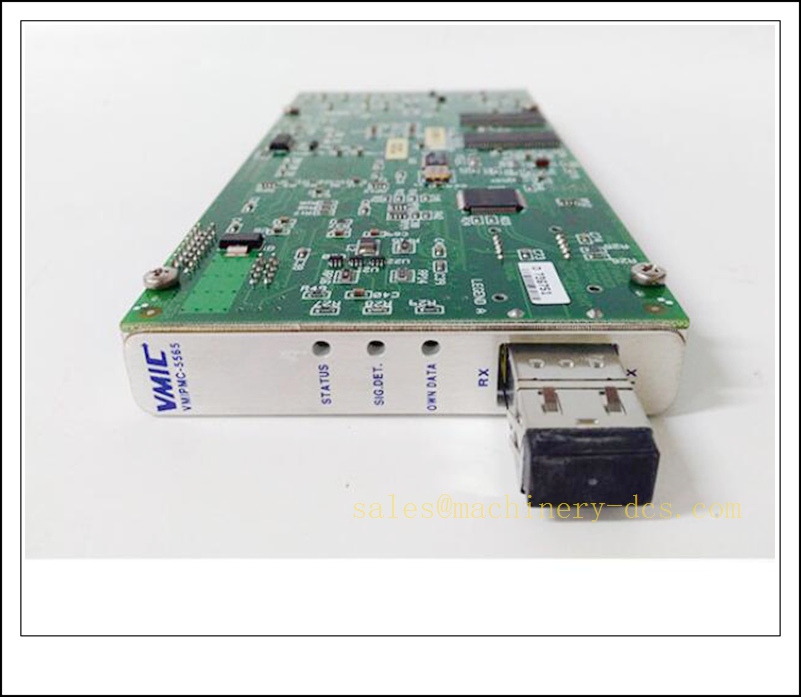
VMIPMC-5565 PMC Reflective Memory Interface Card, Industrial Automation Spare Part
Product Core Overview
The VMIPMC-5565 is a high-performance PMC-format reflective memory interface card manufactured by GE Intelligent Platforms (formerly SBS / VMIC). It provides real-time shared-memory networking for rugged industrial, military and simulation systems.This card transfers data deterministically across multiple nodes on a reflective memory fibre ring with ultra-low latency, ideal for distributed simulation, test benches, motion synchronisation and high-speed inter-controller data exchange. It is widely deployed in VME / VPX embedded control racks. The VMIPMC-5565 series is end-of-life and mainly supplied as tested spare parts for legacy industrial and simulation platforms, supporting rapid replacement to resume synchronous system operation.
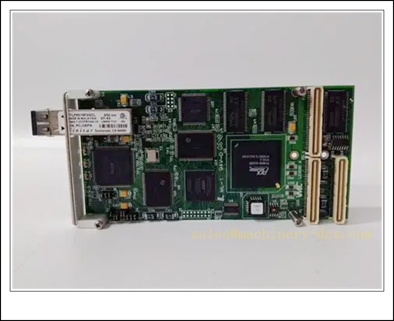
VMIPMC-5565
Main Technical Specifications
| Item | Specification |
|---|---|
| Brand | GE Intelligent Platforms (VMIC) |
| Model | VMIPMC-5565 |
| Form Factor | PMC (PCI Mezzanine Card) |
| Product Type | Reflective Memory Fibre Interface Card |
| Memory Size | 128 MB onboard reflective memory |
| Bus Interface | PCI 33 MHz / 66 MHz, 32-bit PMC interface |
| Network Medium | Fibre optic ring |
| Data Transfer Mode | Deterministic reflective memory broadcast |
| Max Nodes per Ring | Up to 256 nodes |
| Typical Latency | Sub-microsecond class synchronous data update |
| Supply Voltage | +3.3 V / +5 V from PMC carrier |
| Operation Temperature | 0 ℃ ~ +70 ℃ (commercial version; extended temp option available) |
| Ambient Humidity | 5%–90% RH, non-condensing |
| Protection Rating | For rack internal installation |
| Mounting | Plug into PMC carrier board (VME / VPX / CompactPCI carrier) |
| Diagnostic | Onboard status LED for power, link and fault |
| Protection | ESD protection, overcurrent protection on PMC interface |
| Application | Real-time simulation, flight test, distributed motion control, industrial test systems, VME-based control racks |
Quality Control Procedure
- Visual Incoming Inspection: Check PCB, fibre transceiver port, PMC edge connector, mounting bracket, label and serial number integrity.
- ESD Controlled Handling: All inspection and testing performed on grounded anti-static workstation with ESD wrist strap.
- Power-on Burn-in Test: Install on compatible PMC carrier, energise continuously for 4 hours; monitor LED status and temperature.
- Fibre Link Test: Pair with another 5565 reflective memory node, verify fibre TX/RX communication.
- Memory & Data Transfer Test: Execute reflective memory write/read and ring broadcast test to validate deterministic data synchronisation.
- Firmware Validation: Confirm onboard firmware revision matches the original system software.
- Driver Compatibility Check: Verify compatibility with target OS (VxWorks, Linux, Windows real-time).
- Data Archiving: Record serial number and full test report, attach inspection sticker, vacuum anti-static packaging.
- Pre-shipment Audit: Double-check model, memory configuration and quantity before dispatch.
Recommended Related Models & Order Codes (15pcs)
- VMIPCI-5565
- VME-5565
- VMIPMC-5576
- VMIPCI-5576
- VMIVME-7750
- VMIVME-7807
- VMIVME-4116
- VMIVME-3122
- VMIC-5565 fibre transceiver kit
- VMIPMC-2565
- SBS-5565
- VMIVME-7452
- VMIVME-7614
- VMIPMC-1553
- VMIPMC-429
Frequently Asked Questions
Q1: Is VMIPMC-5565 interchangeable with VMIPCI-5565?A: Core reflective memory protocol is identical. Form factor differs (PMC vs PCI). They cannot plug into the same carrier directly; driver and API are largely compatible.
Q2: Is this card discontinued?A: Yes, GE/VMIC VMIPMC-5565 is end-of-life. Available stock is original surplus or fully tested refurbished spare parts.
Q3: Can I hot swap this PMC card while the host rack is powered?A: PMC is not hot-plug by default for most legacy VME carriers. Power down the carrier and follow LOTO before replacement.
Q4: Link LED stays off after installation, what should I check?A: Inspect fibre cable TX/RX crossover, fibre cleanliness and bend radius, ring termination, card ID rotary switch and driver loading status.
Q5: Warranty terms?A: Original surplus new: 12-month warranty. Refurbished tested stock: 6-month warranty. Damage caused by ESD, incorrect fibre wiring, incompatible carrier or firmware mismatch is excluded.
Q6: Which driver and software are used?A: GE VMIC Reflective Memory drivers, supporting VxWorks, Linux and Windows RT. Original system configuration and node ID map must be retained.
Installation & Configuration Guide
Pre-installation Preparation
- Confirm rack environment: clean, low dust, no condensation, away from high EMI sources.
- Prepare ESD protection, insulated screwdriver, matched reflective memory fibre cables and system configuration backup.
- Record all node IDs and reflective memory address mapping before removing the faulty card.
Installation Steps
- Execute LOTO lockout-tagout procedure, cut off power to the PMC carrier and host rack.
- Unplug fibre optic cable, remove the retention screw, extract the faulty PMC card vertically.
- Unpack new spare under ESD protection; avoid touching gold fingers and fibre transceiver face.
- Align the PMC card with the carrier slot, insert smoothly and fasten the mounting screw.
- Connect fibre cable following TX to RX cross wiring for the reflective memory ring.
- Route fibres carefully, maintain minimum bend radius and avoid sharp edges.
- Check carrier power and grounding.
Configuration & Commissioning
- Restore rack power and observe front panel status LEDs.
- Boot host controller and load the GE reflective memory driver.
- Set the correct node ID via rotary switch or software configuration to match the original topology.
- Scan reflective memory ring, confirm all 5565 nodes are detected.
- Run write/read test across the ring to verify synchronous memory update between nodes.
- Validate user application data exchange and real-time synchronisation.
- Clear communication alarms after system self-diagnosis passes.
- Resume application operation and save commissioning log.
Maintenance Notes
- Keep fibre end faces clean; contamination causes intermittent link loss. Use dedicated fibre cleaning supplies only.
- Do not touch the PMC gold fingers directly.
- Do not apply liquid cleaners to PCB.
- Store spare PMC cards in dry sealed anti-static packaging with fibre port caps fitted.

 Send an Email