
Description
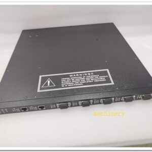
Bently Nevada 3500/65‑01‑00‑R0(16‑Channel Temperature Monitor)
Product Description
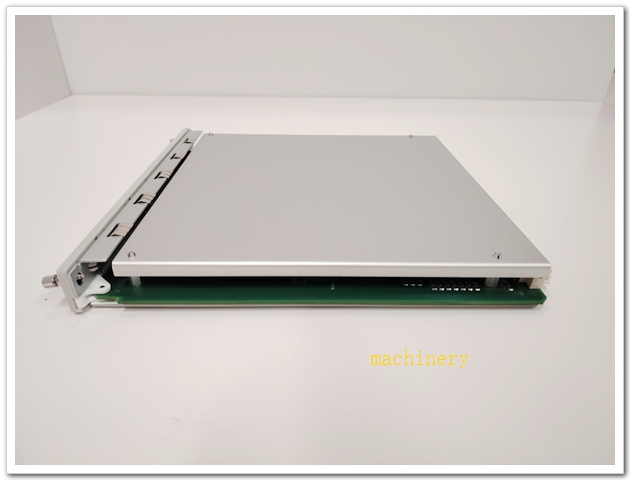
3500/65‑01‑00‑R0(internal part number 145988‑02)is a 16‑channel temperature monitor for the 3500 machinery‑protection rack system. It must mate with rear I/O assembly 172103‑01 (Internal Termination). It supports RTD and isolated‑tip thermocouple inputs, monitors bearing‑bush temperature, stator winding temperature and other thermal parameters of rotating machinery. It provides Alert / Danger alarm setpoints, transmits measurement values and alarm status over rack backplane to relay‑output and TDI communication modules. It supports TMR triple‑modular‑redundant safety‑critical protection configuration and complies with API 670 turbomachinery‑protection standardm.french.p….
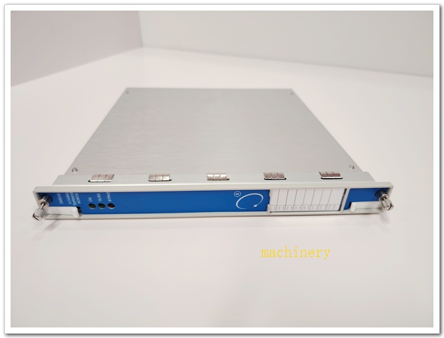
BENTLEY 350065 145988-02
Ordering code decode
| Segment | Meaning |
|---|---|
| 3500/65 | Series: 16‑Channel Temperature Monitor |
| 01 | Rear I/O type: Internal Termination(mate with 172103‑01) |
| 00 | No additional agency certification option |
| R0 | Hardware revision R0 |
Technical Specifications
| Item | Parameter |
|---|---|
| Model | 3500/65‑01‑00‑R0 |
| Internal PN | 145988‑02 |
| Matching Rear I/O | 172103‑01(Internal Termination);172109‑01(External Termination, alternative)Baker Hugh… |
| Channel count | 16 independent temperature channels |
| Sensor support | Pt100 / Ni120 / Cu10 RTD(2‑wire /3‑wire /4‑wire);Isolated‑tip thermocouple J,K,T,E,R,S,B |
| Measuring range | RTD:‑200 ~ +850 °C;TC:‑270 ~ +1800 °C |
| Accuracy | ±3 °C @ 25 °C ambient temperaturem.french.p… |
| Alarm function | Per‑channel Alert / Danger setpoints; configurable alarm delay |
| Power consumption | Nominal 3 W, powered by rack backplane |
| Operating temperature | ‑30 °C ~ +65 °C |
| Storage temperature | ‑40 °C ~ +85 °C |
| Humidity | 5‑95 % RH, non‑condensing |
| Certifications | API 670, CE, UL; capable for SIL3 under TMR voting configurationBaker Hugh… |
| Mechanical | Full‑height 3500 rack module, hot‑swap compatible; weight approx.0.91 kg |
| Front‑panel LED | OK, TX/RX, BYPASS |
| Configuration tool | Bently Nevada 3500 Rack Configuration Software |
| Country of Origin | USA |
| Warranty | 12‑month OEM warranty |
Main Features and Advantages
Key Features
- 16‑channel high‑density temperature acquisition; each channel can be independently configured for RTD or isolated‑tip thermocouple sensor.
- Supports 2‑wire/3‑wire/4‑wire RTD connection; channel‑to‑channel galvanic isolation reduces ground‑loop interference.
- Dual‑level Alert/Danger alarm with configurable delay to suppress false alarms caused by signal transient disturbance.
- Two optional rear‑I/O versions: internal termination (172103‑01) or external termination (172109‑01), adapt to different cabinet wiring schemesBaker Hugh….
- TMR‑compatible architecture; three identical 3500/65 assemblies installed in adjacent slots to implement triple‑modular‑redundant protection loops for SIL‑3 safety requirements.
- Hot‑swap for full front‑rear assembly; replacement without rack power‑down.
- Deep integration with whole 3500 platform; temperature data and alarm events shared via backplane with relay‑output module and 3500/22M TDI communication module.
Core Advantages
‑ High‑density 16‑channel design saves precious rack slots compared with 6‑channel 3500/61 temperature monitor. ‑ Unified rack‑based temperature monitoring, no extra standalone temperature acquisition instruments required; shares power, relay and communication resources with vibration / process‑variable monitors. ‑ Two termination options for flexible engineering implementation for new‑build and retrofit projects. ‑ Complies with API 670 standard for critical turbomachinery bearing‑temperature protection. ‑ Hot‑swap maintainability shortens downtime during module maintenance.
Application Fields
‑ Oil & Gas: centrifugal compressors, gas turbines, steam turbines; bearing‑bush metal‑temperature monitoring for on‑shore / offshore compressor‑station rotating assets. ‑ Power Generation: thermal‑power & combined‑cycle plants; turbine‑generator bearing temperature, stator‑winding temperature supervision. ‑ Petrochemical: refineries, ethylene plants; turbo‑expanders, large pumps and blowers thermal‑condition monitoring and alarm interlock. ‑ Heavy‑industry: chemical plants, steel‑making facilities; multi‑point temperature monitoring for critical rotating‑machinery.
Related Matching Parts
- 172103‑01: Rear I/O assembly with internal termination(mandatory for 3500/65‑01‑00)Baker Hugh…
- 172109‑01: Rear I/O assembly with external termination(alternative option)Baker Hugh…
- 3500 system accessories: 3500/05 rack chassis, 3500/15 redundant power‑supply, 3500/33 relay‑output module, 3500/22M TDI communication module.
- Field sensors: Pt100 RTD, isolated‑tip thermocouples(J/K/T/E).
- Companion monitors: 3500/42M vibration monitor, 3500/62 process‑variable monitor.
Installation and Maintenance
Installation
- Mate 3500/65‑01‑00‑R0 front‑plane board with matched rear‑I/O assembly (172103‑01), insert complete unit into full‑height slot of 3500 rack. For TMR redundant application, install three identical assemblies in adjacent rack slots.
- Route shielded RTD / thermocouple field cables to rear‑I/O terminals. Separate low‑level temperature‑signal wiring from high‑power cables to avoid EMI interference; follow single‑point‑grounding specifications.
- Configure each channel sensor type, engineering‑unit range, filter parameters, Alert/Danger alarm thresholds and alarm‑delay via 3500 Rack Configuration Software, download configuration to rack backplane.
- Verify front‑panel OK‑LED status; perform sensor‑simulation test to confirm measurement accuracy and alarm‑trigger performance before commissioning.
Maintenance
- Hot‑swap replacement supported: set relevant monitor channels to bypass status before extracting the complete front‑rear paired assembly; install new matched assembly, reload configuration parameters as needed; rack power‑off is not required.
- Periodically inspect rear‑I/O terminals and field‑sensor cables for looseness, oxidation or insulation damage.
- Routinely observe front‑panel LED indicators; investigate fault, bypass or abnormal‑alarm status promptly.
- Keep rack ventilation unobstructed; ensure operating temperature and humidity stay within rated specifications.
- Conduct periodic loop‑verification: input reference‑simulation signals to check measurement accuracy and alarm‑response behaviour.
- For defective hardware, return complete front‑rear assembly to authorized‑service channels; do not disassemble internal circuit boards on‑site.

 Start Chat


 Send an Email


