
Description
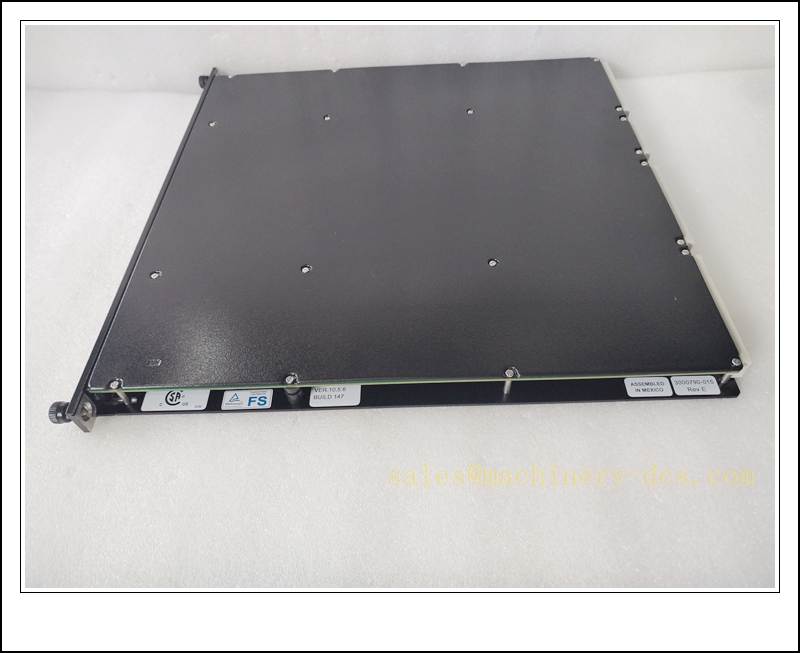
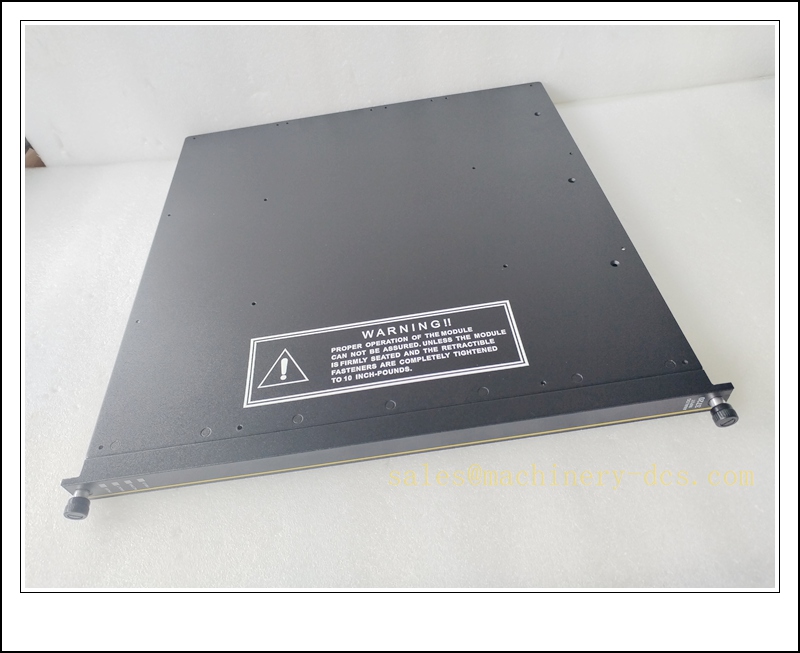
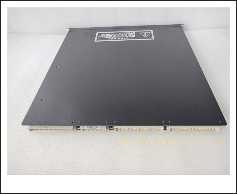
Triconex 3720 High Density TMR Analog Input Module, SIL 3 SIS 64 Single-Ended AI Module
Product Description
The Triconex 3720 is a triple modular redundant (TMR) high-density analog input module designed for the Tricon safety instrumented system. It acquires continuous process signals from field transmitters, supporting 0–5 VDC voltage signals or 4–20 mA current signals with an external 250 Ω shunt resistor. The module employs three independent signal acquisition paths with 2oo3 mid-value voting to reject single hardware faults without interrupting safety monitoring. It converts analog field measurements into digital values and transmits validated data to the Tricon main processor via the triplicated TriBus backplane. Comprehensive on-board diagnostics detect out-of-range signals, open circuits, short circuits, overvoltage and internal leg faults. This module supports hot-swap operation while the rack remains online, enabling maintenance for continuous process plants without safety system shutdown. It requires an external termination panel (ETP) and ribbon cable assembly for field wiring termination.
TRICONEX 3720
Technical Specifications
- Brand: Triconex (Schneider Electric)
- Model: 3720
- Module Type: High Density Analog Input (AI)
- Architecture: TMR Triple Modular Redundancy, mid-value selection voting
- Channel Count: 64 single-ended input channels
- Signal Types: 0–5 VDC; 4–20 mA (with 250 Ω external shunt)
- Resolution: Software selectable 12-bit / 14-bit
- Accuracy: ≤0.15% full scale range at 0 °C to +60 °C
- Sampling / Update Rate: 10 ms per channel
- Input Impedance: 10 MΩ minimum for voltage mode
- Overvoltage Protection: Continuous 150 VDC / 115 VAC
- Field-to-System Isolation: 800 VDC minimum
- Diagnostics: Signal over-range, under-range, open circuit, short circuit, module self-test, leg fault detection
- Backplane Interface: Tricon triplicated TriBus
- Hot Swap: Supported with fully healthy online rack
- Operating Temperature: 0 °C to +60 °C
- Storage Temperature: -40 °C to +85 °C
- Relative Humidity: 5% to 95%, non-condensing
- Safety Certification: SIL 3 capable per IEC 61508
- Configuration Software: TriStation
- Power Source: Powered via Tricon chassis backplane
- Power Consumption: Less than 12 W
Application Scenarios
- Petrochemical and refinery ESD safety monitoring of pressure, flow and temperature transmitters
- Onshore and offshore oil & gas SIS and fire & gas monitoring systems
- Power plant boiler, gas turbine and generator safety instrumented functions
- LNG terminal and cryogenic process critical analog measurement loops
- Pipeline pressure and temperature safety monitoring
- Continuous chemical plant safety transmitter signal acquisition
- Hazardous Class I Div 2 / Zone 2 SIS control cabinets
- High channel-count safety systems requiring SIL 3 fault tolerant analog input
8 Related Triconex Model Recommendations
- 3703E – 8-Channel Analog Input Module
- 3704E – 8-Channel Analog Output Module
- 3504E – 64-Point High Density Commoned Digital Input Module
- 3604E – 16-Channel Non-Commoned Digital Output Module
- 3805E – Tricon Main Processor Module
- 4000098-510 – Tricon Redundant Power Supply
- 3707A – Digital Output Module
- 3721 – Communication Interface Module
Compatibility & Installation Pitfalls
Compatibility
- Exclusive to Tricon TMR chassis and TriBus backplane; incompatible with Bently 3500 and other third-party SIS racks.
- Requires Tricon firmware version v10.2 or later for proper recognition and to maintain SIL 3 certification.
- Must pair with the matching external termination panel and ribbon cable set.
- For 4–20 mA inputs, external 250 Ω shunt resistors must be fitted on the ETP; the module does not include built-in shunts.
- Application logic and I/O configuration reside in the main processor; the module does not store logic locally.
- SIL 3 safety integrity depends on a complete healthy TMR rack; standalone module cannot perform SIL 3 functions.
Installation Pitfalls
- Hot-swap is permitted only when all three processor legs are fault-free; avoid hot-swap during active SIF critical operation or system faults.
- This is single-ended input architecture; ground potential differences between cabinet and field transmitters create ground loops and unstable readings.
- When using 4–20 mA mode, missing or incorrect 250 Ω shunt resistors will produce invalid voltage readings.
- Analog field wiring must be segregated from high-power AC and VFD cables; induced noise causes signal drift and spurious high/low alarms.
- Do not exceed the continuous 150 VDC /115 VAC overvoltage rating; overvoltage events can permanently damage input circuitry.
- Module mechanical keying prevents insertion into wrong slot; never force the module into an incompatible backplane connector.
- Channel diagnostics only detect electrical circuit faults; transmitter drift and sensor calibration decay must be verified via regular proof-test.
- Over-range reading capability extends to +6% above nominal span; do not rely solely on over-range diagnostics as a primary process trip.
TRICONEX 3720
Standard Operating Procedure (SOP)
SOP for 3720 Analog Input Module Inspection, Installation and Functional Test
- Pre-Installation Inspection Inspect the module for physical damage, connector pin deformation or contamination. Confirm the part number matches the SIS design package. Verify the corresponding external termination panel and ribbon cable assembly. Review transmitter signal type, shunt resistor requirements and safety trip logic. Apply lockout-tagout to associated SIS shutdown circuits before rack access.
- Rack Installation Power down the rack if the module supports a critical safety loop with no redundant I/O path. Insert the 3720 into the designated Tricon I/O slot and engage the locking latch. Connect the ribbon cable from the rear module connector to the external termination panel. Terminate transmitter wiring on the ETP, install 250 Ω shunts for 4–20 mA channels. Separate low-level analog signal wiring from high-energy power cables and apply shielding per approved SIS drawings.
- Software Configuration Open TriStation and upload the existing Tricon application. Map the 3720 in the I/O configuration table. Select voltage or current mode, configure engineering units, high/low alarm and trip thresholds, and enable signal range diagnostics. Download the validated application to the main processor and resolve all I/O configuration fault codes. Archive the safety application file for IEC 61508 audit traceability.
- Channel Calibration and Signal Injection Test Isolate field transmitters as required. Inject low, mid and high span signals to each channel. Confirm readings in TriStation match the injected values within specified accuracy tolerance. Simulate open circuit and short-circuit conditions to verify fault reporting. Confirm out-of-range signals trigger the configured diagnostic alarms.
- Safety Interlock Verification Reconnect field transmitters. Inject trip setpoint signals and confirm the SIS executes the designed shutdown sequence. Confirm TMR voting suppresses single leg faults and prevents spurious trips. Record all calibration accuracy, diagnostic response and trip test results in the SIS proof-test log.
- Return to Service Clear all temporary test forces and diagnostic latches. Remove lockout tags and restore the safety monitoring loop to online status. Monitor module health and analog channel stability for the required observation period. Notify operations that high-density analog safety measurement is active.
- Periodic Maintenance and Replacement During planned outages, inspect ETP terminal torque, cable shielding and shunt resistor integrity. Repeat signal injection calibration and range diagnostic tests per the site SIS proof-test schedule. If persistent unrecoverable TMR leg faults occur, confirm rack health before hot-swap. After installing a replacement module, confirm automatic synchronization with the Tricon processor, reload validated I/O configuration and re-run the full calibration and trip test before releasing the module to safety duty.

 Start Chat


 Send an Email


