
Description
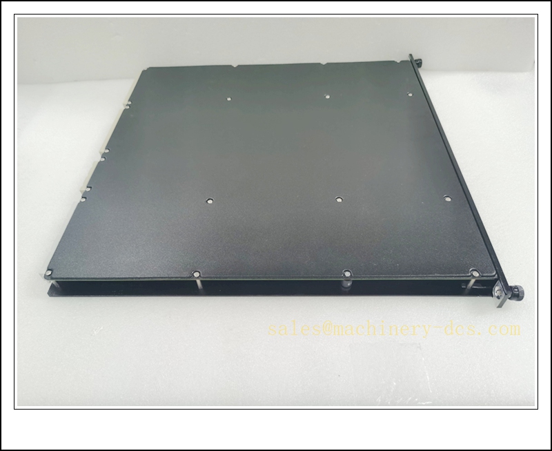
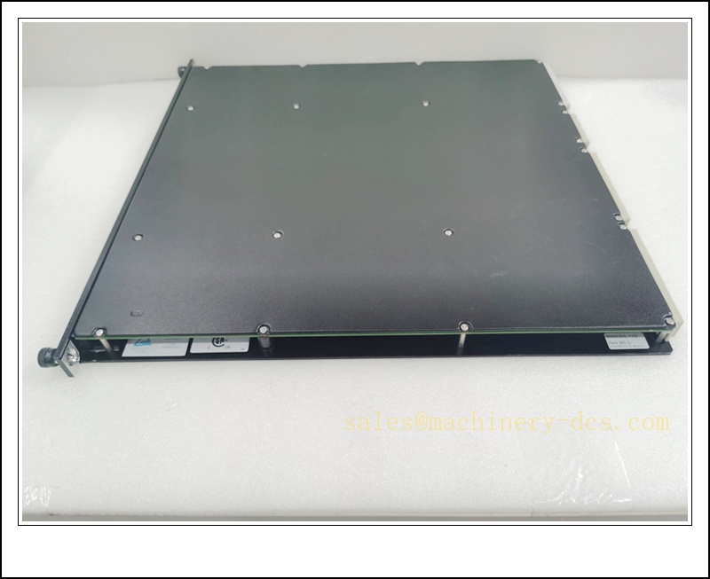
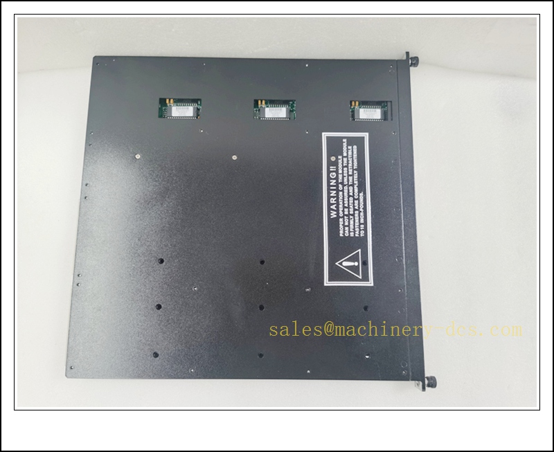
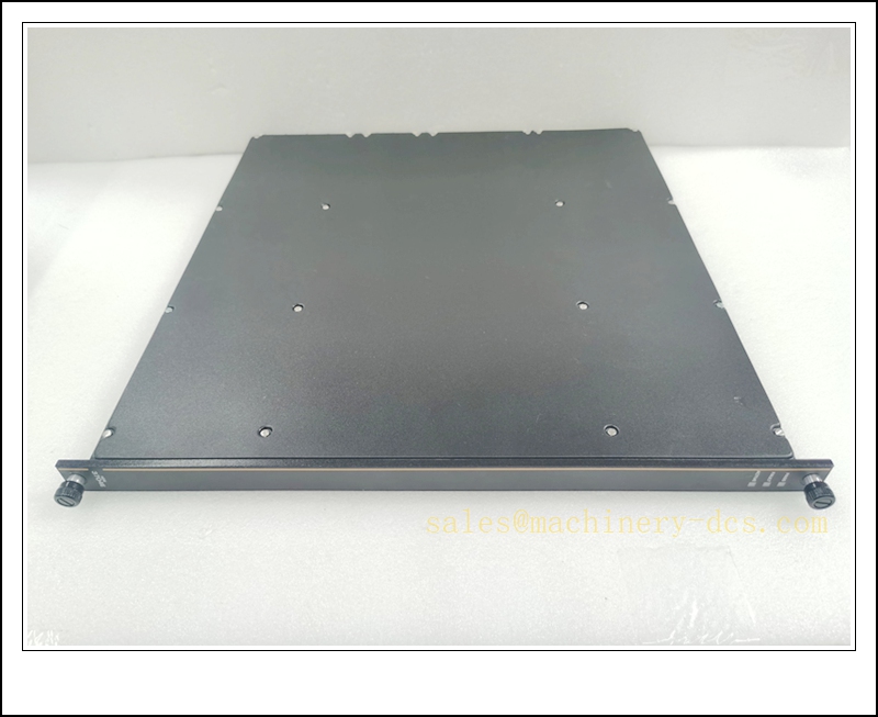
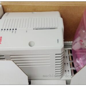
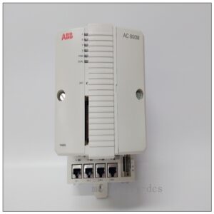
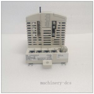
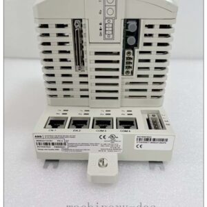
Triconex 3704E Analog Output Module, TMR Safety System Module for Tricon SIS
Product Description
The 3704E is a triple modular redundant (TMR) analog output module designed for the Triconex Tricon safety instrumented system (SIS). It receives digital control values from the Tricon main processor and converts them into isolated 4–20 mA analog field signals to drive control valves, I/P converters, positioners and other process final control elements. Built on Triconex proprietary triple-vote architecture, three independent signal channels execute the same output calculation simultaneously; the module votes on the valid signal to suppress single-point faults while maintaining safety function. Comprehensive on-board diagnostics detect open circuits, short circuits, over-range outputs, backplane communication faults and internal hardware failures. Fault status is reported to the Tricon main chassis for alarm and diagnostic logging. It supports hot-swap under online operation, allowing module replacement without tripping the safety system, which is essential for continuous process plants. This module fits into the standard Tricon chassis backplane and communicates via the Tricon triplicated system bus.
3704E
Technical Specifications
- Brand: Triconex
- Model: 3704E
- Module Type: Analog Output (AO)
- Architecture: TMR Triple Modular Redundancy
- Number of Channels: 8 analog output channels
- Output Signal: 4–20 mA, configurable range
- Resolution: 16-bit
- Accuracy: ±0.1% of full span at normal operating conditions
- Isolation: Channel-to-backplane isolation, galvanically isolated field side
- Load Resistance: Max 750 Ω per channel for 4–20 mA
- Backplane Interface: Tricon TMR system bus
- Power: Supplied from Tricon chassis backplane
- Hot Swap: Supported when the Tricon rack remains online
- Operating Temperature: 0 °C to +60 °C
- Storage Temperature: -40 °C to +85 °C
- Relative Humidity: 5% to 95%, non-condensing
- Safety Certification: SIL 3 capable for IEC 61508 safety loops
- Diagnostic Coverage: High diagnostic coverage for open/short circuit and internal faults
- Configuration Tool: Triconex TriStation software suite
Application Scenarios
- Petrochemical and refinery SIS emergency shutdown (ESD) valve control
- Oil & gas onshore/offshore process safety interlock systems
- Power plant boiler and turbine safety control loops
- Chemical batch and continuous process safety instrumented functions
- Pipeline pressure and flow safety regulation via analog final elements
- Hazardous area Class I Div 2 / Zone 2 safety control cabinets
- LNG terminal and cryogenic process ESD and BMS (Burner Management System)
- Critical plant control where TMR fault tolerance and SIL 3 integrity are required
8 Related Triconex Model Recommendations
- 3703E – 8-Channel Analog Input Module
- 3706A – Digital Input Module
- 3707A – Digital Output Module
- 3805E – Tricon Main Processor Module
- 4000098-510 – Tricon Power Supply Module
- 3708E – High Density Digital Input Module
- 3721 – Communication Interface Module
- 3501 – Tricon Chassis Backplane Assembly
Compatibility & Installation Pitfalls
Compatibility
- Only compatible with Triconex Tricon TMR chassis and corresponding backplane; not compatible with Bently 3500 rack or other PLC/SIS platforms.
- Requires matching TriStation software firmware revision for the main processor and I/O modules to preserve SIL certification.
- Works with 4–20 mA field devices such as valve positioners, I/P transducers; confirm field device loop impedance before commissioning.
- TMR modules must be used within a complete Tricon fault-tolerant rack; a standalone 3704E cannot implement SIL 3 functions.
- Mixing of different Tricon I/O families in the same rack is permitted, but safety loops must maintain approved TMR architecture.
- Configuration is stored in the main processor, not locally on the 3704E; replacement module does not require reloading logic.
Installation Pitfalls
- Hot-swap is allowed only when the Tricon rack is fully online with all three processor legs healthy; do not hot-swap during a known system fault condition.
- Do not exceed the maximum 750 Ω loop resistance for 4–20 mA outputs; excessive load causes signal clamping and loss of control.
- Analog output field wiring must be segregated from high-power AC, VFD and relay cables; induced noise can cause output drift and valve hunting.
- Mismatched ground potentials between the SIS cabinet and field transmitters create ground loops and unstable mA signals; follow single-point isolation rules.
- Fault indication LED does not verify correct valve response; diagnostics only detect electrical faults, not mechanical valve sticking or actuator failure.
- Verify that the output failsafe state (fail-high / fail-low) is configured correctly in TriStation; misconfigured failsafe will defeat the safety loop design.
- Field wiring short-circuits can trigger module channel fault; excessive repeated short events may permanently damage output circuitry.
- Do not use this module for direct high-power load driving; analog outputs are low-energy control signals only, must interface to I/P or solenoid drivers.
3704E
Standard Operating Procedure (SOP)
SOP for 3704E Analog Output Module Inspection, Installation and Functional Test
- Pre-Installation Inspection Inspect the module for physical damage, connector pin deformation or contamination. Confirm the part number and TMR marking match the SIS design package. Review loop drawings, field device impedance and safety requirements. Apply lockout-tagout to associated control and shutdown circuits before rack access.
- Rack Installation Power down the Tricon rack if this module supports a critical safety loop with no redundant I/O path. Insert the 3704E into the designated I/O slot and secure the retaining latch. Terminate 4–20 mA field wiring to the rear terminal assembly. Separate analog control wiring from high-voltage power circuits and apply shielding per approved SIS drawings.
- Software Configuration Open TriStation software and upload the existing Tricon application. Confirm the 3704E is mapped in the I/O configuration table. Set each channel’s output range, engineering units and defined failsafe value. Download the validated application to the Tricon main processor and resolve all I/O configuration fault codes. Archive the safety application file for IEC 61508 audit and traceability.
- Loop Calibration and Signal Injection Test With field devices isolated where required, force output values from TriStation. Verify 4 mA, 12 mA and 20 mA are measured accurately at the module terminals and field device side. Simulate wire break and short-circuit conditions to confirm the module reports channel diagnostics as designed. Confirm the channel reverts to the configured failsafe state on fault.
- Final Element Functional Verification Reconnect field actuators and positioners. Force setpoints and confirm valve stroke, position feedback and response match the control demand. Confirm that Tricon fault voting logic does not produce unexpected valve action during single-leg module diagnostics. Record all calibration, accuracy and failsafe test results in the SIS proof-test log.
- Return to Service Clear all temporary test faults and force values. Remove lockout tags and restore the safety control loop to online status. Monitor module diagnostic status and analog output stability for the required observation period. Notify operations that analog control and failsafe functions are active.
- Periodic Maintenance and Replacement During planned outages, inspect terminal torque, cable shielding and field loop integrity. Repeat mA calibration and failsafe testing per the site SIS proof-test schedule. If the module reports persistent unrecoverable TMR faults, confirm the rack is healthy before hot-swap. After installing a replacement module, verify auto-sync with the Tricon processor, re-run the full loop and failsafe test before releasing to safety duty.

 Start Chat


 Send an Email


