
Description
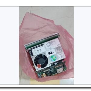
PacDrive 3 LMC400C Series Multi‑Axis Motion Controller
Brand: Schneider Electric (ELAU)
Model: LMC400Cxxxxxxx (xxxxxxx = configurable variant suffix, e.g. LMC400CAA180RC)
Product Series: PacDrive 3 Motion Control System
Country of Origin: Germany
Product Type: DIN‑rail mount real‑time motion / robot controller
Product Core Overview
The LMC400C series is a high‑performance real‑time motion controller for PacDrive 3 servo drive systems, originally developed by ELAU and integrated under Schneider Electric. It executes IEC 61131‑3 standard logic, multi‑axis synchronisation, electronic cam, gearing, robot kinematics and sequence control.
The suffix xxxxxxx defines axis license count, robot function, hardware revision and option codes (e.g. LMC400CAA180RC = 180 license‑points robot‑enabled version). It supports real‑time Ethernet motion bus, local onboard I/O, multiple field‑bus interfaces, HMI connection and host‑system data exchange. Widely used for packaging machinery, material‑handling, robotics, printing and converting lines, for new‑machine build and existing PacDrive 3 retrofit spare‑part replacement.
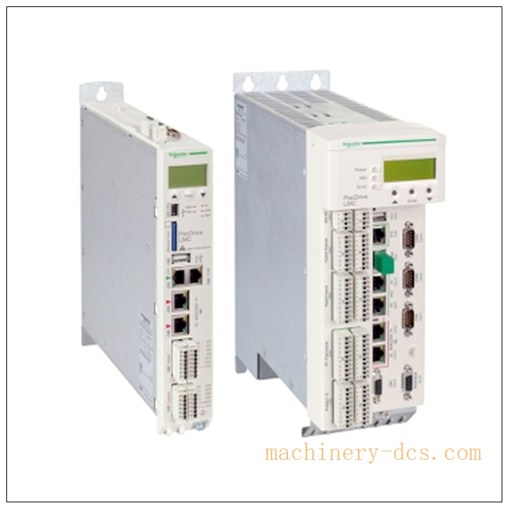
LMC400C
Main Technical Specifications
| Parameter | Specification |
|---|---|
| Manufacturer | Schneider Electric (ELAU) |
| Model | LMC400Cxxxxxxx (variable suffix defines options) |
| Product Family | PacDrive 3 Motion Controller |
| Control Standard | IEC 61131‑3, CODESYS runtime |
| Max Motion Axis | Up to 16 axes (depends on license‑point variant)rexelcdn.b… |
| Robot Function | Robot kinematics support (model‑dependent license) |
| On‑board Digital Inputs | 20 DI; 4 interrupt inputs; 16 touch‑probe inputs (20‑33 VDC)rexelcdn.b… |
| On‑board Digital Outputs | 16 DO, 250 mA per channel |
| On‑board Analog I/O | 2 AI / 2 AO, ±10 V / 4‑20 mA, 12‑bit resolution |
| Communication Interfaces | 2 × Real‑time Ethernet (motion bus), PacNet, Ethernet TCP/IP, CANopen, PROFIBUS‑DP, RS232, RS422/485, USB‑A |
| Power Supply | 24 VDC, typical < 1 A |
| Mounting | DIN‑rail cabinet mounting |
| Protection Class | IP20 (cabinet installation only) |
| Operating Temperature | 0 °C … +55 °C |
| Storage Temperature | −25 °C … +70 °C |
| Weight | approx 3.5 kg |
| Certifications | CE, UL, CSA |
| Warranty | 12‑month manufacturer warranty |
Note: Exact axis quantity, license‑points and robot capability are determined by the full complete part‑number suffix (replace
xxxxxxx). Hardware revision must match during spare‑part replacement to avoid incompatibility.
PacDrive 3 LMC400 Series Related Models
- LMC400CAA150RC: Motion‑controller, 80 license‑points, robot‑capable
- LMC400CAA180RC: Motion‑controller, 240 license‑points, robot‑capable (common variant)
- LMC400CABxxxx: Standard motion controller without robot license
- LMC400Bxxxx: Compact lower‑performance LMC400 variant
- SH3xxxx: PacDrive 3 servo motor series
- C400xxxx: PacDrive 3 servo drive power unit
- VW3Mxxxx: Motion‑bus cable & accessory series
Professional Quality Control & Test Standard Operating Procedure (SOP)
- Incoming Component Inspection Inspect main CPU, memory, communication transceivers, I/O circuits and connectors. Verify compliance with Schneider‑ELAU industrial component specifications; reject non‑conforming components.
- PCB Assembly & Bench Functional Test After SMT assembly, perform power‑on boot test. Validate IEC‑runtime startup, each digital/analog channel, all communication port physical‑layer behaviour. Simulate motion‑bus traffic to verify real‑time link stability.
- Thermal Burn‑in Aging Test 72‑hour powered burn‑in at 50 °C ambient. Run cyclic multi‑axis motion simulation, field‑bus traffic and I/O toggling. Monitor CPU temperature, memory integrity and communication link quality to screen early‑life hardware failures.
- Environmental Compliance Validation Temperature cycling, mechanical vibration/shock and EMC testing per IEC 61000‑6‑2 / IEC 60068 standards, simulating factory cabinet harsh‑environment conditions.
- Full‑System PacDrive 3 Integration Test Pair LMC400C with C400 servo drives. Test real‑time motion bus, axis synchronisation, cam‑profile execution, robot kinematics, field‑bus master/slave operation, onboard‑I/O logic and fault‑diagnosis reporting.
- Final Calibration & Batch Sampling Release Calibrate analog‑channel offset/gain. 5 % random‑sample retest per batch. Record hardware revision, serial‑number and license‑point information. Generate traceable factory‑test records before labelling and shipment.
New Unit Installation Guidelines
6.1 Pre‑installation Preparation
Power‑off cabinet 24 VDC supply. Wear anti‑static wristband for ESD protection. Verify full part‑number and hardware‑revision matches original unit (critical for spare‑part swap). Inspect for mechanical damage, bent pins or corrosion. Prepare shielded motion‑bus cables, Ethernet cables and insulated screwdriver.
6.2 Hardware DIN‑rail Installation
Clip LMC400C onto standard DIN‑rail. Lock DIN‑rail latch. Wire 24 VDC power supply. Route motion‑bus, field‑bus and I/O cables separately from high‑power drive cables to minimise EMI interference. Terminate bus terminators as per wiring manual.
6.3 Software Configuration & Commissioning
Power‑on the controller. Launch Schneider Machine‑Expert / PacDrive engineering software. Establish online connection. Confirm controller license‑points and feature set match project requirements. Download application project, axis‑parameters, cam‑profiles and robot kinematics. Execute offline simulation first; then perform real‑axis jog test, verify synchronisation and robot‑movement behaviour. Backup complete project offline.
6.4 Post‑installation Validation
Check front‑panel LED status indicators (RUN, FAULT, BUS). Verify onboard‑I/O status, field‑bus data exchange and motion‑bus link status. Run continuous 4‑hour runtime test. Confirm no communication drop‑outs, no unexpected faults or axis‑following errors. Complete commissioning acceptance.
Application Scenarios & Product Features
Application Scenarios
- High‑speed packaging machinery, filling‑lines, carton‑handling equipment
- Converting, printing and paper‑processing production machines
- Multi‑axis robotic handling, pick‑and‑place applications
- Material‑handling and automated assembly systems
- PacDrive 3 system upgrade and spare‑part replacement projects
- Machine‑builder standard automation platform for complex motion sequences
Core Features
- IEC 61131‑3 standard programming with CODESYS‑based runtime
- Real‑time multi‑axis motion control: electronic‑gearing, cam‑profiles, synchronisation
- Optional integrated robot‑kinematics (subject to model‑license)
- Rich onboard digital‑/analog‑I/O plus expandable I/O capability
- Multiple real‑time and standard field‑bus interfaces for drives, HMI and host PLC
- PacDrive 3 native motion‑bus for tight‑synchronised servo‑drive control
- Onboard touch‑probe high‑speed input for position‑capture applications
- DIN‑rail compact cabinet‑mount form‑factor for machine‑panel integration
Frequently Asked Questions (FAQ)
Q1: Controller boots but RUN LED stays off, FAULT LED red
A1: Check 24 VDC supply voltage. Confirm hardware‑revision compatibility. Check project download integrity; review diagnostic buffer in Machine‑Expert. Perform full power‑cycle. If fault persists return for hardware inspection.
Q2: Motion‑bus link unstable, axis communication errors
A2: Check motion‑bus cable integrity and shielding grounding. Verify bus‑terminator installation. Separate motion‑signal wiring from high‑power cables. Check network topology; avoid excessive cable‑length.
Q3: Cannot use robot‑kinematics functions
A3: Confirm full part‑number includes robot license option. Check license‑point count in controller information. Re‑download valid licence file if required. Some LMC400C variants do not include robot capability.
Q4: Spare‑part replacement: can I use different hardware‑revision unit?
A4: Not recommended. Mismatched hardware‑revision may cause incompatibility with existing project firmware/software. Always match hardware‑revision as per nameplate data.
Q5: Onboard analog‑channels read incorrect values
A5: Verify analog‑signal wiring and ground reference. Check configuration for voltage/current mode. Perform analog‑channel offset calibration via engineering‑tool.
Q6: What routine maintenance is required for LMC400C?
A6: Every 3‑6 months inspect cabinet ventilation and dust accumulation; check terminal‑screw tightness. Keep full project backup files. Avoid continuous over‑temperature cabinet‑operation. Do not clean circuit‑boards with liquid solvents. Periodically review controller diagnostic logs.

 Start Chat


 Send an Email


