
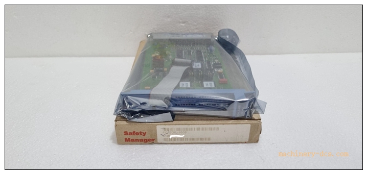
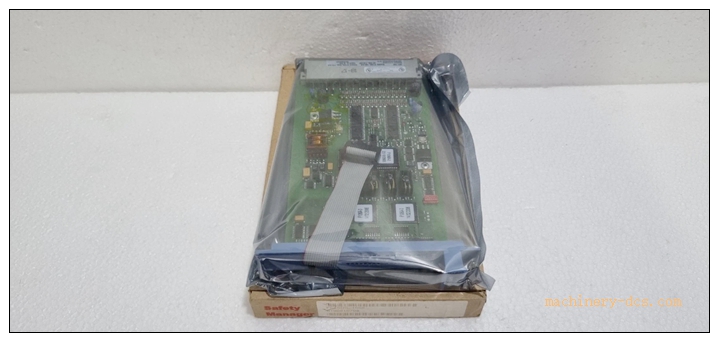
Description
Honeywell FC‑SDIL‑1608 24VDC (FC‑SDIL‑1608) Safe Loop‑Monitored Digital Input Module
Title
Honeywell FC‑SDIL‑1608 24VDC 16‑Channel SIL3 Loop‑Monitored Safety Digital Input Module
Meta‑Description
Honeywell FC‑SDIL‑1608 24VDC is a 16‑channel loop‑monitored safety digital input module for Honeywell FSC / Safety Manager SIS system, 24VDC input, TÜV‑certified SIL3 IEC61508, supports wire‑break, short‑circuit and earth‑fault diagnostics, used for safety‑critical discrete signal acquisition for emergency stop, limit switches and NAMUR proximity sensors in petrochemical and process safety instrumented systems.
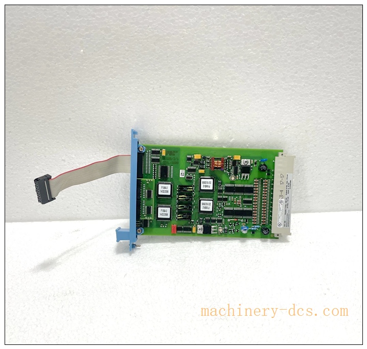
FC‑SDIL‑1608
Product Core Overview
FC‑SDIL‑1608 24VDC (FC‑SDIL‑1608) is a safety‑grade loop‑monitored digital input I/O module belonging to Honeywell FSC / Safety Manager safety‑instrumented system family. It provides 16 independent monitored digital input channels for acquiring discrete safety‑related field signals including emergency‑stop buttons, limit switches, dry‑contact interlocks and NAMUR‑compliant proximity sensors.
This module integrates comprehensive channel‑level diagnostics for open‑circuit, short‑circuit and earth‑fault detection on field wiring, which can identify cable failures before triggering safety trips. Each channel is equipped with front‑panel LED status indicators for fast‑on‑site troubleshooting. Certified up to SIL3 per IEC 61508, it is widely deployed in petrochemical, oil‑gas and chemical process plants for SIS safety interlock protection. It plugs into FSC backplane carrier and communicates with safety controller via fault‑tolerant internal safety bus. Signal conversion accessories BN‑1608 / BSN‑1608 are required for NAMUR sensor signal conditioning.
Main Technical Specifications
| Item | Parameter |
|---|---|
| Part Number | FC‑SDIL‑160824VDC (FC‑SDIL‑1608) |
| Module Type | Loop‑Monitored Safety Digital Input Module |
| Compatible System | Honeywell FSC / Safety Manager SIS System |
| Input Channels | 16 channels, loop‑monitored |
| Rated Input Voltage | 24 VDC (0‑30 VDC working range) |
| Max Channel Input Current | 2 mA |
| Typical Response Time | 25 ms |
| Diagnostics | Wire‑break detection, short‑circuit detection, earth‑fault monitoring |
| Safety Certification | TÜV SIL3, IEC 61508 / IEC 61511, CE |
| LED Indicators | Channel status LED, module health / fault LED |
| Power Consumption | Max 10 W |
| Operating Temperature | −40 °C ~ +70 °C |
| Storage Temperature | −40 °C ~ +85 °C |
| Relative Humidity | 5 %‑95 % non‑condensing |
| Vibration / Shock | 0.5 g rms 5‑200 Hz; 15 g 11 ms half‑sine pulse |
| Mounting | FSC rack backplane slot installation |
| Required Accessory | BN‑1608 / BSN‑1608 converter for NAMUR signal inputs |
Quality Control Procedures
- Visual & Mechanical Incoming Inspection: Visual inspection for PCB conformal coating, backplane connector, front‑panel LED assembly and part‑number labeling. Unique serial‑number recorded for full‑lifecycle traceability.
- Backplane Interface Continuity Test: Verify pin continuity, insulation and isolation performance of FSC backplane connector.
- Channel‑by‑Channel Functional Calibration: Inject simulated 24 VDC discrete signals for every channel; validate input threshold accuracy and signal acquisition performance.
- Diagnostic Logic Verification: Simulate field‑loop faults: open‑circuit, short‑circuit and earth‑fault conditions; confirm fault‑reporting and LED indication work correctly.
- Safety‑bus Communication Test: Validate reliable safety‑data exchange between module and Safety Manager / FSC controller.
- Environmental Stress Screening: Temperature‑cycle test covering full operating temperature range for thermal stability verification.
- EMC Compatibility Test: Test under industrial electromagnetic‑interference environment to guarantee stable safety‑signal acquisition.
- Final End‑of‑Line Validation & Archiving: Complete full‑function test suite, all test data archived bound to unit serial‑number before factory release.
Related Brand Model Recommendations
- FC‑SDO‑0824: Safety digital output module, 8‑channel 24VDC safety output, matched output counterpart for FC‑SDIL‑1608.
- BN‑1608 / BSN‑1608: Signal converter accessories, required for NAMUR proximity‑sensor signal conditioning.
- FC‑SDI‑1624: Standard non‑loop‑monitored 16‑channel safety digital‑input module, without line‑break monitoring function.
- Matching Controller: Honeywell Safety Manager / FSC safety processor unit.
- System Accessories: FSC rack carrier, backplane bus‑connectors, safety termination terminal blocks.
Frequently Asked Questions (FAQ)
Q1: What field devices can connect to FC‑SDIL‑160824VDC? A: It accepts dry‑contact switches, emergency‑stop contacts, limit‑switches. For NAMUR proximity sensors, BN‑1608 or BSN‑1608 signal converter must be installed in the field‑loop circuit.
Q2: What diagnostic functions does this module support? A: Each channel monitors wire‑break, short‑circuit and earth‑fault on field cables. Fault status will be reported to SIS controller for alarm and event logging.
Q3: Is hot‑swap supported? A: Physical hot‑plug hardware is mechanically possible, but under safety‑running system state, module replacement requires safety‑logic bypass operation strictly following Honeywell SIS operating manual. Not allow blind hot‑swap without bypass.
Q4: What is the safety‑level rating? A: TÜV certified for SIL3 according to IEC 61508, suitable for safety‑instrumented‑system safety interlock applications.
Q5: Can I use FC‑SDIL‑1608 on other DCS brands rack? A: No. It is exclusively designed for Honeywell FSC / Safety Manager backplane rack, cannot work on third‑party DCS racks.
Q6: Can I repair the module on‑site? A: No. It is factory‑calibrated safety‑grade PCB assembly. Unauthorized disassembly will void SIL‑certification and warranty. Return defective units to authorized service‑centre.
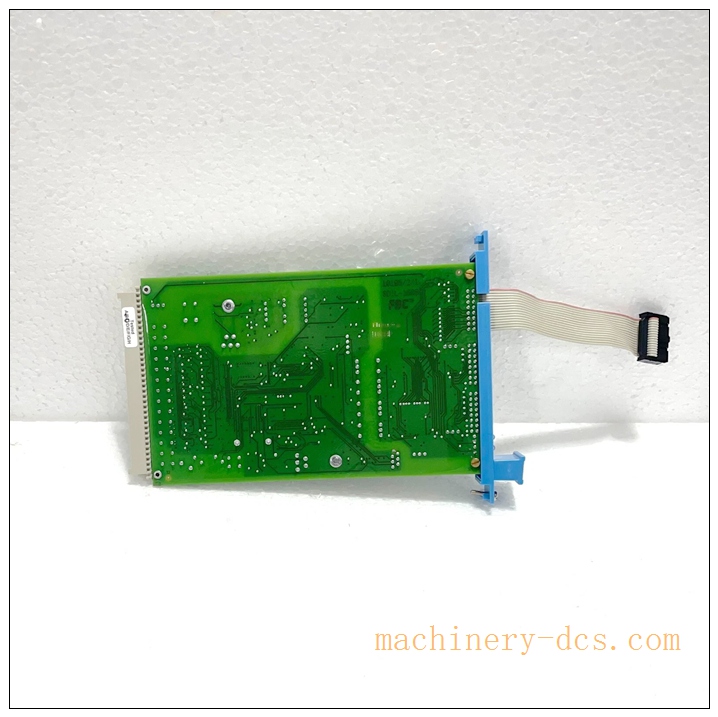
FC‑SDIL‑1608
Installation & Configuration Guide
Pre‑Installation
- Inspect module for transit damage. Confirm part‑number FC‑SDIL‑160824VDC and serial‑number match purchase‑order.
- Confirm FSC / Safety Manager rack, carrier‑backplane and safety‑processor are fully functional.
- Prepare field devices: dry‑contact switches or NAMUR sensors with BN‑1608/BSN‑1608 converters, safety‑rated screened field cables.
- Review SIS safety drawing, define channel assignment, fault‑diagnostic‑action logic and safety‑bypass strategy.
Mechanical Installation
- Insert FC‑SDIL‑160824VDC into designated FSC rack carrier slot, push firmly until backplane‑connector fully mates. Tighten front‑panel captive fasteners.
Important: Before module replacement in running SIS system, execute related safety‑bypass procedure as per project safety manual.
Electrical Wiring
- Route safety‑field screened cables to safety‑termination block, separate safety‑signal wiring from high‑power‑cable routes to reduce EMI interference.
- For NAMUR sensors, install BN‑1608 / BSN‑1608 converter in field‑loop. Strictly follow wiring‑diagram.
- Complete continuity and insulation‑resistance check for each input‑loop before power‑on. Implement single‑point grounding for screen/shield.
System Configuration & Commissioning
- Launch Honeywell Safety Manager configuration software and connect to SIS controller.
- Add FC‑SDIL‑1608 module in corresponding rack‑slot position within project hardware‑configuration.
- Configure each channel: enable/disable loop‑diagnostic functions, define fault‑response logic, download configuration to safety‑processor.
- Field‑loop commissioning: trigger each field‑switch / sensor status change, verify corresponding channel‑LED and SIS‑software status change correctly.
- Inject simulated loop‑faults (open‑circuit / short‑circuit / earth‑fault), verify fault‑alarm reporting and diagnostic‑event logging.
- Complete safety‑bypass function test as required. Save full‑project configuration backup file, then place module into formal safety‑interlock operation.

 Start Chat


 Send an Email


