
Description
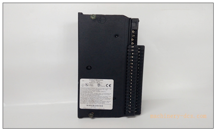
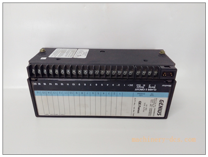
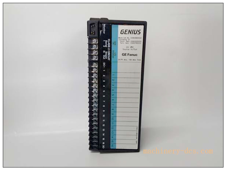
GE‑Fanuc (Emerson) IC660BRD021 Genius 24/48 VDC 16‑Circuit Sink I/O Block (Redundancy‑Capable)
Brand: GE‑Fanuc (Emerson)
Model: IC660BRD021
Product Series: Genius Distributed I/O System
Country of Origin: USA
Product Type: Discrete Sink‑type DC remote I/O block for Genius bus
Status: Obsolete / Discontinued original production; only spare‑part, refurbished & surplus supply
Product Core Overview
The IC660BRD021 is a 16‑channel sink‑type discrete DC I/O block for GE‑Fanuc Genius distributed fieldbus system. It works on Genius 153.6 kbaud serial bus, compatible with Series 90‑30 / 90‑70 PLC Genius scanner hosts.
16 configurable sink‑type channels can be set as input or output via Genius hand‑held monitor or PLC configuration software. It supports redundancy‑T output wiring for high‑availability applications. Built‑in channel‑level diagnostics, overcurrent electronic protection, selectable input filter times and output test function. Widely deployed in power plants, heavy‑industry, water‑treatment for legacy Genius distributed‑I/O spare‑part replacement and retrofit projects.
IC660BRD021
Main Technical Specifications
| Parameter | Specification |
|---|---|
| Manufacturer | GE‑Fanuc / Emerson |
| Model | IC660BRD021 |
| Channel count | 16 circuits, configurable sink‑type DI / DO |
| Field power range | 24‑48 VDC nominal (18‑56 VDC operating range) |
| Output rating | 2 A per channel; max 10 A inrush for 10 ms; overcurrent shutdown >15 A /10 ms |
| Input impedance | 1.8 kΩ @24 VDC; 5.6 kΩ @48 VDC |
| Input filter | Software‑selectable filter time |
| Bus interface | Genius serial bus, 153.6 kbaud |
| Isolation | 1500 V between block‑to‑block; 300 V group‑to‑group isolation |
| Hand‑held monitor port | D‑sub for Genius HHM configuration & diagnostics |
| LED indicators | Unit OK LED + per‑channel I/O status LEDs |
| Power dropout tolerance | 10 ms |
| Max power dissipation | 68.8 W |
| Mounting | Screw‑mount inside control cabinet; allow upside‑down installation |
| Dimensions | 224.4 mm(H) ×90.5 mm(W) ×112.3 mm(D) |
| Weight | approx 0.54 kg |
| Protection class | IP20 (cabinet‑only installation) |
| Operating temperature | 0 °C ~ +60 °C |
| Storage temperature | −40 °C ~ +85 °C |
| Humidity | 5‑95 %RH, non‑condensing |
| Certifications | CE, UL listed |
| Warranty | 12‑month |
Genius BRD‑series related models
- IC660BRD021: 24/48 VDC 16‑circuit sink block, redundancy‑T capable (reference model)
- IC660BRD020: 24/48 VDC 16‑circuit source block, redundancy‑T capable
- IC660BBD021: Standard non‑redundant 24/48 VDC sink block
- IC660BBD020: Standard non‑redundant 24/48 VDC source block
- IC660BEM002: Genius bus scanner module for Series 90‑70 PLC
- HHM: Genius hand‑held monitor for local block configuration
Professional Quality Control & Test Standard Operating Procedure (SOP)
- Incoming Component Inspection Inspect main logic board, Genius bus transceiver, sink output power circuits, field‑side terminal block and HHM port. Verify components comply with GE‑Fanuc industrial grade specifications; reject non‑conforming components.
- PCB Assembly & Bench Functional Test After assembly, perform power‑on self‑test. Simulate Genius bus communication with Genius scanner host. Test each of 16 channels under both input‑mode and output‑mode; verify overcurrent protection trigger, selectable input‑filter, output test function and channel‑level diagnostic reporting. Validate HHM hand‑held monitor local configuration access.
- Thermal Burn‑in Aging Test 72‑hour powered burn‑in test at 55 °C ambient. Run cyclic channel toggle and continuous Genius‑bus traffic. Monitor thermal drift of power circuits and bus‑communication stability, screen early‑life hardware defects.
- Environmental Compliance Validation Temperature cycling, vibration‑shock and EMC EMI/EMS testing comply with GE‑Genius system standards for heavy‑industry cabinet environment.
- Full‑system Genius‑bus integration test Connect IC660BRD021 to Series 90‑70 Genius scanner. Configure partial‑redundancy T‑output wiring simulation. Verify cyclic I/O data exchange, fault‑diagnostic bit feedback, redundancy‑mode operation and front‑panel LED status indication.
- Final calibration & batch‑sampling release Validation of hardware revision and firmware version; 5 % random‑sample retest per batch. Record serial‑number. Generate traceable factory‑test reports before labelling and shipment.
Installation Guidelines
Safety note: Power‑off Genius bus and field 24‑48 VDC power before installation / removal. Do not hot‑swap this block. Observe isolation requirements for field wiring.
6.1 Pre‑installation Preparation
Switch‑off Genius bus power and field DC power. Wear anti‑static wristband for ESD‑protection. Verify full part‑number IC660BRD021 matches spare‑part requirement; confirm hardware revision. Inspect for mechanical damage, terminal pin bending. Prepare Genius hand‑held monitor (HHM), field wiring diagram, Genius bus cable.
6.2 Hardware Cabinet‑mount Installation
Mount I/O block inside cabinet with 8‑32 screws & star washers for proper grounding. Maintain ≥2 inch clearance between adjacent blocks for cooling. Terminate Genius bus cable; install bus terminator at physical bus‑segment endpoints. Route field‑signal cables separate from high‑power AC cables. Wire 24‑48 VDC field power and field‑device wiring strictly follow Genius redundancy‑T wiring drawing if redundant‑output mode is used.
6.3 System Configuration & Commissioning
Power‑up Genius bus and field power. Connect Genius hand‑held monitor to block HHM port. Set block Genius bus address, configure each channel as input or output, set input‑filter time, enable redundancy‑T mode if required. Download Genius‑bus configuration into PLC host scanner. Bring Genius bus online; verify cyclic I/O data exchange between PLC and field‑side channels. Test output‑test function and channel fault‑diagnostic reporting. Save complete Genius‑bus configuration offline for backup.
6.4 Post‑installation Validation
Check front‑panel Unit‑OK LED and per‑channel status LEDs. Verify input‑signal reading and output‑drive performance. Simulate field‑wiring fault conditions to validate block diagnostics. Run continuous 4‑hour runtime test. Confirm no bus‑communication errors, no false diagnostics, complete commissioning acceptance.
IC660BRD021
Application Scenarios & Product Features
Application Scenarios
‑ Heavy‑industry, power‑plant auxiliary control, water‑treatment Genius distributed‑I/O system ‑ High‑availability control‑loops requiring redundancy‑T output wiring ‑ Connecting solenoid valves, relays, proximity sensors, discrete field switches ‑ Legacy GE Genius I/O system spare‑part replacement and field‑retrofit projects
Core Features
‑ 16‑channel sink‑type discrete I/O, each channel configurable as DI or DO ‑ Support Genius Redundancy‑T output wiring for high‑reliability control loops ‑ Wide field supply range: 18‑56 VDC (24/48 VDC nominal) ‑ Per‑channel electronic overcurrent protection with fault‑diagnostic feedback ‑ Software‑selectable input‑filter time for noise suppression ‑ Built‑in output‑test capability for field‑loop verification ‑ 1500 V block‑to‑block isolation for noise immunity ‑ Local configuration via Genius hand‑held‑monitor (HHM) port ‑ Per‑channel LED status indication for fast on‑site troubleshooting ‑ Compatible with GE Series 90‑30 / 90‑70 Genius‑bus host scanners
Frequently Asked Questions (FAQ)
Q1: Unit‑OK LED off after power‑on
A1: Check Genius bus power supply and field‑side 24‑48 VDC power. Verify Genius bus terminator installation. Confirm block bus‑address no conflict with other Genius nodes. Perform full system power‑cycle. If fault persists return unit for hardware inspection.
Q2: Some outputs cannot drive field loads
A2: Confirm channel configured as output mode (not input). Check field‑supply voltage within 18‑56 VDC range. Verify no channel overcurrent protection has tripped; read block diagnostic bits. Review redundancy‑T wiring correctness if running redundant‑output configuration.
Q3: Can replace IC660BBD021 directly?
A3: Physically pin‑compatible; BRD021 adds Redundancy‑T output function. If original project does not use T‑redundancy, direct swap is possible. If T‑redundancy is required, must use BRD‑series block.
Q4: Genius bus communication intermittent errors
A4: Check Genius bus cable integrity, shielding‑grounding and bus‑terminator installation. Avoid running Genius bus cable parallel with high‑power cables. Check for excessive number of nodes on single Genius drop.
Q5: What routine maintenance is required for ?
A5: Every 6‑12 months inspect cabinet ventilation and dust accumulation; check terminal‑screw tightness and Genius‑bus connector. Backup full Genius‑bus configuration. Avoid long‑term cabinet over‑temperature operation. Do not clean circuit‑boards with liquid solvent. Periodically monitor Genius‑bus diagnostic error counters.

 Start Chat


 Send an Email


