
Description
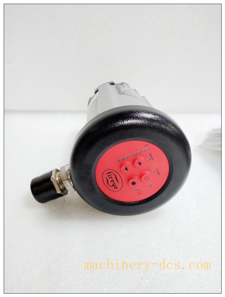
FIREYE 85UVF1A‑1QDK3 Phoenix Series‑II UV Flame Scanner with K3 Enhanced Optical Filter
Product Detailed Description
The 85UVF1A‑1QDK3 is a microprocessor‑driven self‑checking integrated ultraviolet flame scanner within Fireye Phoenix Series‑II product family. It features special K3 optical filter, optimized for complex combustion environments with high background infrared and visible light interference, suitable for low‑NOx burners, waste‑gas firing and mixed‑gas fuel conditionsFireye. This unit integrates UV sensor, flame signal processing logic, self‑diagnostic circuit, relay outputs and 4‑20 mA analog transmitter inside one cast‑aluminum housing. Adopts 8‑pin QD quick‑disconnect connector, enables fast field replacement without hard‑wired cable re‑termination. Supports automatic flame‑signature learning, configurable flame failure response time (FFRT). It is FM / UL / CE certified for Class I Division 2 hazardous locations when mated with qualified 59‑546‑XX QD field cables. Still active spare‑part offering; new‑old‑stock, refurbished and field‑pulled units circulate for power‑plant, refinery and industrial boiler maintenance & retrofit projects.
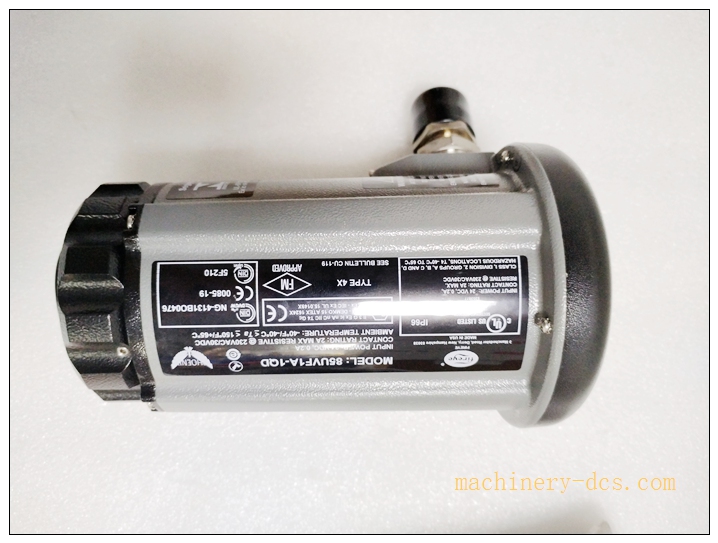
85UVF1A-1QDK385UVF1A-1QDK3
Technical Parameters
| Item | Specification |
|---|---|
| Manufacturer | FIREYE (United States) |
| Model | 85UVF1A‑1QDK3 |
| Series | Phoenix Series‑II |
| Detection Spectrum | UV 295‑340 nm, K3 enhanced filter for IR/visible‑light rejectionFireye |
| Power Supply | 24 VDC ±20 %, typical consumption 200 mA |
| Output Interface | SPST‑NO Flame Relay; SPST‑NC Fault Relay; optically‑isolated 4‑20 mA flame‑strength analog output, max load 750 Ωstaging.fi… |
| Contact Rating | Max 2 A @ 230 VAC resistive load; min 10 mA @ 5 VDC |
| FFRT | Configurable: 1 s / 2 s / 3 s / 4 s |
| Response Performance | Rapid flame‑on detection; auto‑gain selection via flame‑learn routine |
| Electrical Connection | 8‑pin QD quick‑disconnect mating to 59‑546‑XX series cables |
| Mechanical Housing | Cast‑aluminum, grey polyester powder coating; IP66 / NEMA 4X |
| Field‑of‑View | 80° conical viewing angle |
| Ambient Operating Temp | ‑40 °C ~ +65 °C electronics; scanner internal max 82 °C with purge‑air cooling |
| Storage Temperature | ‑40 °C ~ +85 °C |
| Relative Humidity | 5‑95 % RH, non‑condensing |
| Purge‑air Requirement | Clean dry cooling air, typical 4 SCFM (113 L/min) via 3/8” NPT port |
| Mounting Interface | 1‑inch NPT female, compatible with flange 60‑2919‑1 / 60‑2692‑1 (sold separately) |
| Weight | Approx. 0.85 kg |
| Certifications | FM Approved, UL Listed, CE, Class I Div 2 hazardous‑area rating (with correct QD cable) |
| On‑board Indicator | Multi‑LED array: flame intensity, ready status, flame relay, fault‑code display |
Compatibility & Installation Pitfalls
Compatibility
- Fireye Phoenix‑series burner‑management safety systems
- Industrial boilers, process heaters, duct‑burners, low‑NOx burners, waste‑gas incinerators, mixed‑gas firing furnaces
- QD‑type field cable: Fireye 59‑546‑XX series 8‑pin quick‑disconnect cable (mandatory for Div 2 hazardous‑area compliance)
- Works with standard BMS / PLC via dry‑contact relay & 4‑20 mA analog loop
Critical note: K3 filter variant cannot be directly swapped with standard 85UVF1‑1QD without re‑performing flame‑learn; optical rejection characteristic differs. Not interchangeable with IR‑type 85IRF series scanners.
Installation Pitfalls
- K3‑filter application constraint: K3 filter suppresses IR interference; do NOT deploy on pure‑luminous heavy‑oil flames, may cause insufficient flame signal amplitude.
- Optical sighting & lens fouling: Aim sensor cone directly toward flame root. Quartz front lens accumulates soot, oil vapour and dust; dirty lens yields gradual signal attenuation and intermittent flame‑loss trips without explicit fault alarm. Periodic cleaning is mandatory.
- QD‑cable matching: Only 59‑546‑XX certified QD cables satisfy Class I Div 2 requirements. Generic 8‑pin connectors void hazardous‑area certification.
- Mandatory auto‑learn procedure: Never skip flame‑learn commissioning step. Copying stored thresholds from other burners will result in unstable detection, false‑flame or spurious flame‑loss shutdowns.
- Purge‑air management: Insufficient cooling purge‑air leads to internal over‑temperature and permanent electronics damage; purge‑air must be clean, dry and oil‑free.
- Wiring polarity risk: 24 VDC reverse polarity will destroy internal circuit; strictly follow terminal polarity marking.
- EMI interference: Route QD signal cable separately from high‑power motor / ignition cables. Heavy electromagnetic noise distorts 4‑20 mA flame‑strength readings.
- Part‑number full‑suffix verification: Confirm complete marking 85UVF1A‑1QDK3. Distinguish from standard 85UVF1‑1QD, 85UVF1‑1QDK3, CEX explosion‑proof variants; suffix letters define filter, connector and hazardous‑area rating.
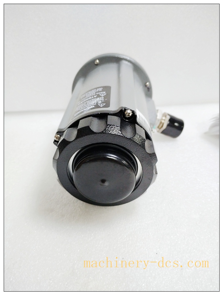
85UVF1A-1QDK3
Standard Operating Procedure (SOP)
- Pre‑work: Apply lock‑out‑tag‑out permit for burner system; shut‑down fuel supply, cut 24 VDC power to scanner.
- Visual incoming inspection: Examine spare scanner housing for mechanical damage, inspect quartz lens for scratches or contamination; verify full part‑number suffix marking.
- Mechanical mounting: Install scanner onto burner sight‑port flange, align viewing cone toward flame root. Secure mounting threads; connect regulated clean cooling‑purge‑air supply.
- Cabling: Connect certified 59‑546‑XX 8‑pin QD quick‑disconnect field cable. Strictly follow wiring diagram for 24 VDC power, flame‑relay, fault‑relay and 4‑20 mA analog loop connections.
- Commissioning auto‑learn: Start burner under stable normal firing condition. Execute scanner automatic flame‑learn routine to capture real‑site flame signature and store detection thresholds. Set required FFRT time parameter.
- Functional validation: Perform flame‑on / flame‑off test cycle. Verify LED status, relay switching action, 4‑20 mA flame‑strength analog output. Simulate flame loss to validate safety‑trip response. Confirm no false‑alarm events under stable combustion.
- Maintenance record: Document learned threshold values and FFRT setting in site commissioning log; establish scheduled quartz‑lens cleaning maintenance item.
- Post‑job: Release lock‑out‑tag‑out permit only after full safety‑function acceptance‑test is successfully completed.
Application Scenarios
‑ Petrochemical refinery process heaters & furnaces with high background‑radiation noise ‑ Utility auxiliary boiler, district‑heating industrial gas‑fired boiler combustion safety supervision ‑ Low‑NOx burners, duct burners, waste‑gas incinerators, mixed‑gas fuel firing equipment ‑ Power‑plant balance‑of‑plant burner safety monitoring ‑ Hazardous‑area Class I Div 2 locations (when paired with approved QD cable assembly) ‑ Plant BMS upgrade and legacy‑Phoenix‑system spare‑part replacement
Matching & Supporting Components
- Fireye 59‑546‑XX series 8‑pin QD quick‑disconnect field cable
- Mounting flange assembly P/N 60‑2919‑1 or 60‑2692‑1
- Replacement quartz lens spare kit
- Clean dry regulated cooling‑purge‑air source
- 24 VDC isolated SELV power supply for flame‑detector loop
- Burner‑management‑system safety controller
Brand‑Related Alternative & Recommended Models
- 85UVF1A‑1QD: Standard‑filter Phoenix‑II QD scanner, no K3 interference‑rejection filter
- 85UVF1‑1CEXK3: Explosion‑proof ATEX‑rated K3‑filter variant for Zone 1 hazardous‑area installation
- 85IRF1A‑1QDK3: K3‑filter infrared scanner for luminous‑rich heavy‑fuel combustion conditions
- 85UVF4A‑1QDK3WR: Weather‑resistant enhanced‑revision Phoenix‑4 scanner for new‑build projects

 Start Chat


 Send an Email


