
Description
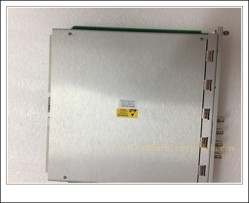
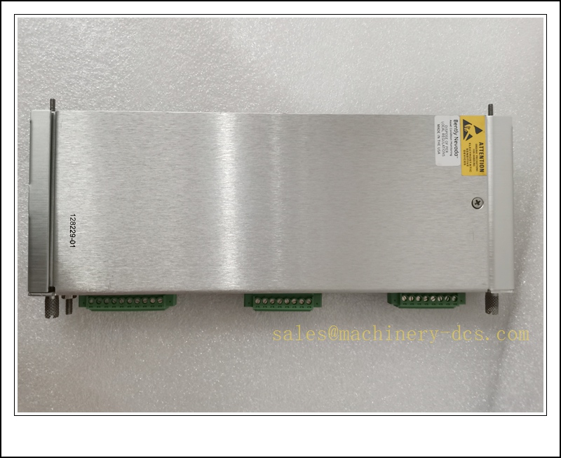
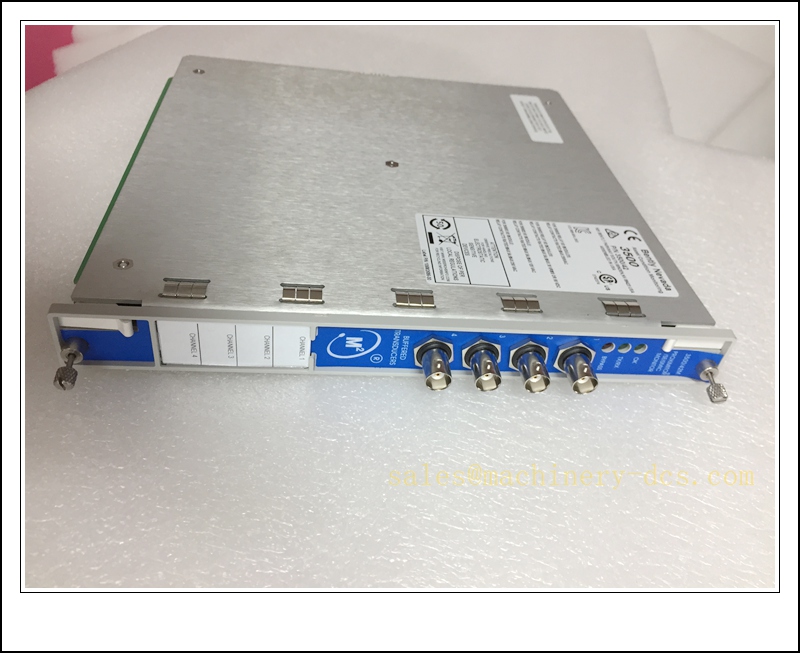
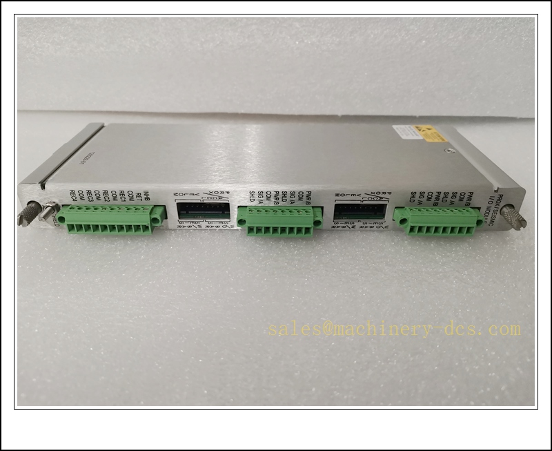
Bently Nevada 3500/42 SIL2-04-00 Proximitor / Seismic 4-Channel Machinery Monitor Module, SIL 2 Rated, Internal Barrier Version for 3500 TSI Rack
Product Description
The 3500/42 SIL2-04-00 is a four-channel programmable Proximitor and Seismic monitor for the Bently Nevada 3500 machinery protection system. It carries SIL 2 capability per IEC 61511 and complies with API 670 for turbine supervisory instrumentation. This variant includes internal signal barriers, accepting signals from eddy-current proximity probes and seismic transducers. Each channel can be configured for radial vibration, thrust position, eccentricity, differential expansion, velocity or acceleration measurements. It processes transducer signals, calculates dynamic machine parameters, generates Alert / Danger alarm outputs, and communicates measured values, status and alarm events over the 3500 proprietary backplane to TDI/EGD gateway modules. It is widely deployed on steam turbines, gas turbines, centrifugal compressors and generators for safety-related machinery protection and trip logic.
Technical Parameters
| Item | Specification |
|---|---|
| Manufacturer | Bently Nevada (Baker Hughes) |
| Model | 3500/42 SIL2-04-00 |
| Function | 4-Channel Proximitor / Seismic Machinery Monitor, SIL2 capable |
| Host Platform | Bently Nevada 3500 Machinery Protection Rack |
| Channel Count | 4 independent programmable channels |
| Transducer Input | Eddy current proximity probes, seismic velocity / acceleration sensors |
| Measurement Modes | Radial Vibration, Thrust Position, Eccentricity, Differential Expansion, Velocity, Acceleration |
| Module Suffix Definition | 04 = Internal barriers and on-board termination; 00 = No hazardous-area option |
| Safety Rating | SIL 2 capable (system architecture dependent, IEC 61511), API 670 compliant |
| Backplane Interface | 3500 proprietary rack backplane |
| Power Source | Supplied via 3500 rack backplane |
| Form Factor | Single-slot plug-in rack module |
| Operating Temperature | 0 ℃ ~ +60 ℃ |
| Storage Temperature | -40 ℃ ~ +85 ℃ |
| Relative Humidity | 5–95% non-condensing |
| Diagnostics | Transducer OK detection, signal overload, self-test, configuration mismatch, watchdog |
| Status Indicator | Front-panel LEDs: OK, Alert, Danger |
| Weight | Approx. 0.91 kg |
Recommended Related Models (8 units)
- 3500/91-01-01-01: TDI Transient Data Interface for waveform capture
- 161204-01: 3500/91 EGD Ethernet gateway for DCS data exchange
- 3500/22M: Keyphasor / phase and speed reference module
- 3500/50: Tachometer speed monitor module
- 3500/15: 3500 rack power supply
- 3500/05: 3500 rack chassis and backplane
- 3300 XL 8mm Proximity Probe: Shaft vibration and position transducer
- 100M2833: 10ft USB configuration cable for 3500 rack
3500/42 SIL2-04-00
Compatibility & Installation Traps
Compatibility
- Primary host system: Bently Nevada 3500 machinery protection rack
- Associated rack modules: 3500/91 TDI/EGD, 3500/22M Keyphasor, 3500/50 speed monitor
- Software: Official Bently 3500 Rack Configuration Software
- Note: SIL2 rating depends on the complete rack architecture, voting logic and proof-test procedures, not only the module itself. The -04 suffix internal barrier version is not pin-compatible with external termination variants; swapping variants requires reworking field wiring.
Critical Installation Traps
- SIL System Architecture Requirement: SIL2 certification applies to the whole protection loop, not the standalone card. Replacement must maintain the approved voting, bypass and proof-test scheme from the site safety requirements specification.
- Internal Barrier Wiring Rule: This -04 variant uses on-board termination. Do not add external isolators or barriers in parallel; this will alter transducer bias and gap voltage and cause false transducer OK faults.
- Configuration Channel Mapping: The replacement module must be loaded with the original channel configuration, including probe sensitivity, full-scale range, Alert/Danger setpoints and alarm latch settings. Mismatched configuration leads to incorrect trip thresholds.
- Keyphasor Signal Dependency: Phase, orbit and synchronous vibration measurements rely on a healthy 3500/22M Keyphasor signal. A noisy or missing Keyphasor creates invalid dynamic data even if the 3500/42 module is fault-free.
- ESD Sensitivity: Analog front-end, signal conditioning and backplane logic are ESD-sensitive. All replacement work must be performed at a grounded ESD workstation with a wrist strap.
- Backplane Slot Assignment: Install only in valid monitor slots. Improper slot placement blocks backplane data transfer to TDI/EGD and prevents alarm publishing to the DCS.
- Transducer Cable Segregation: Probe extension cables must be separated from high-current VFD and solenoid wiring. Electrical noise causes gap drift, intermittent transducer dropout and spurious vibration alarms.
- Hot Swap Limitation: While many 3500 rack revisions support hot swap, removing this monitor in a live protection loop can disable machine trip functions. Confirm plant lockout and bypass procedures before extraction.
Standard Operating Procedure (SOP)
- Pre-installation inspection: Inspect front panel, PCB and backplane connector for burn marks or mechanical damage. Confirm full part number 3500/42 -04-00 against the site spare register.
- Configuration backup: Export the complete rack setup, channel assignments, transducer sensitivity, alarm setpoints and relay logic using the 3500 configuration software.
- System preparation: Implement approved safety bypasses for the affected machinery protection loops, notify control room and obtain work permit for SIL-related work.
- Energy isolation: If hot swap is not permitted, de-energize the 3500 rack power supply and apply lockout/tagout. Allow internal capacitors to discharge before module removal.
- Mechanical replacement: Release ejector latches and extract the faulty monitor. Insert the replacement 3500/42 -04-00 fully into the designated monitor slot and seat the backplane connector.
- Power-up and self-test: Restore rack power. Observe front panel OK, Alert and Danger LEDs. Execute module self-test and verify backplane communication with TDI/EGD and other rack modules.
- Channel and loop validation: Load saved channel configuration. Verify transducer gap voltage, OK status, vibration/position readings and alarm trip points. Test alarm relay action and EGD/TDI data transmission.
- Process qualification: Perform static and dynamic machine tests, cross-check readings with local indications and confirm no unintended machine trips. Remove safety bypasses only after full validation.
- Decommissioning: Pack the defective module in anti-static shielding bags and label with fault symptoms for failure analysis. Archive the latest rack configuration file.
3500/42 SIL2-04-00
Application Scenarios
- -rated turbine supervisory protection for steam turbines, gas turbines, centrifugal compressors and generators
- Continuous monitoring of shaft radial vibration, thrust position, eccentricity and differential expansion
- Seismic velocity and acceleration measurement for bearing housing vibration
- Alarm generation and trip voting logic for critical rotating machinery
- Data delivery to System 1 condition monitoring software and DCS via 3500/91 TDI or EGD gateway
- Preventive maintenance spare stocking for API 670 TSI systems in power, oil & gas and petrochemical plants
- Troubleshooting of transducer faults, spurious vibration alarms, signal overload and backplane communication issues
- Commissioning and proof-testing of machinery protection loops
Supporting Components
- ESD wrist strap, anti-static shielding bags and conductive work mat
- 3500 rack ejector latches and screwdriver set
- 3500/15 rack power supply
- 3300 XL proximity probe, extension cable and mounting hardware
- Bently Nevada 3500 configuration software and USB service cable (100M2833)
- 3500/22M Keyphasor module and transducer cable assembly
- 3500/91 TDI or EGD gateway module and industrial shielded Ethernet cable
- Safety bypass documentation and SIL loop proof-test forms

 Start Chat


 Send an Email


