
Description
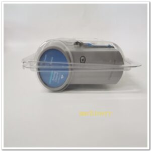
Allen‑Bradley 1756‑L75 ControlLogix Controller, Industrial Automation Spare Part
Product Core Overview
The 1756-L75 is a high-performance ControlLogix L7-series CPU controller under Rockwell Automation. It has 32 MB user memory, supporting up to 100 CIP motion axes, designed for large-scale discrete, process and coordinated motion control applications. It has no built-in Ethernet port; communication relies on separate communication modules (EN2T, CN2 etc.). It adopts SD card for non-volatile program backup and capacitor-based ESM energy storage module instead of traditional battery. It supports redundant configuration with 1756-RM redundancy module, widely used in automobile, packaging, water treatment, petrochemical and power industries.This model is mature lifecycle; many users treat it as legacy spare for existing ControlLogix racks.
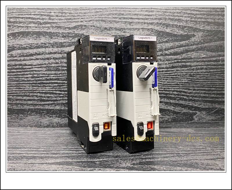
1756-L75
Main Technical Specifications
| Item | Specification |
|---|---|
| Brand | Allen‑Bradley (Rockwell Automation) |
| Model | 1756-L75 |
| Series | ControlLogix 5570 |
| Product Type | PLC CPU Controller |
| User Memory | 32 MB |
| I/O Memory | 0.98 MB |
| Max Controlled Axes | 100 axes (CIP Motion over EtherNet/IP) |
| Max Total I/O | 128,000 points |
| Local Port | 1 × USB (for programming only) |
| Non-volatile Storage | SD card (1784-SD1 / SD2) |
| Power Consumption | 2.5 W |
| Power Draw | 800 mA @ 5.1 VDC, 5 mA @ 1.2 VDC |
| Energy Backup | 1756-ESMCAP capacitor module |
| Operating Temperature | 0 ℃ ~ +60 ℃ (standard version) |
| Ambient Humidity | 5%–95% RH, non-condensing |
| Protection Rating | IP20, chassis slot installation |
| Mounting | Standard 1756 ControlLogix chassis slot |
| Diagnostic | Status display screen, RUN/OK/SD/FAULT LEDs, key switch |
| Software | Studio 5000 / RSLogix 5000 |
| Application | Assembly line, packaging machine, process plant, coordinated multi-axis motion system |
Quality Control Procedure
- Visual Incoming Inspection: Check front display, USB port, SD slot, key switch, chassis gold finger, label and serial number integrity.
- ESD Controlled Handling: All inspection and testing performed on grounded anti-static workstation with ESD wrist strap.
- Power-on Burn-in Test: Install into compatible 1756 chassis, energise continuously for 4 hours; monitor LED status and temperature.
- Chassis Backplane Communication Test: Verify communication with I/O and communication modules.
- Program & SD Card Test: Load user program, verify program read/write and SD card backup/restore function.
- Motion Axis Resource Test: Confirm axis resource allocation matches specification.
- Firmware Compatibility Check: Confirm firmware revision matches the existing project and Studio 5000 version.
- Data Archiving: Record serial number and full test report, attach inspection sticker, vacuum anti-static packaging.
- Pre-shipment Audit: Double-check model, firmware version and whether XT / standard variant before dispatch.
Recommended Related Models & Order Codes (15pcs)
- 1756-L74 (16MB Controller)
- 1756-L73 (8MB Controller)
- 1756-L72 (4MB Controller)
- 1756-L71 (2MB Controller)
- 1756-EN2T EtherNet/IP Module
- 1756-CN2 ControlNet Module
- 1756-RM Redundancy Module
- 1756-A10 10-slot Chassis
- 1756-PA75 Power Supply
- 1784-SD1 SD Card 1GB
- 1756-ESMCAP Energy Storage Capacitor
- 1756-IB32 Digital Input
- 1756-OB32 Digital Output
- 1756-IF16 Analog Input
- 1756-OF8 Analog Output
Frequently Asked Questions
Q1: Can 1756-L75 replace 1756-L74 directly?A: Same L7 series platform, only memory and max axis quantity differ. Confirm program size, axis configuration, firmware version and Studio 5000 compatibility before replacement.
Q2: Does 1756-L75 support hot swap?A: ControlLogix chassis supports hot swap of the CPU module, but the controller will stop running, all logic, motion and I/O control will drop out. Process shutdown, safety lockout and risk assessment are mandatory.
Q3: FAULT alarm after installation, what should I check?A: Check chassis power supply, backplane contact, firmware compatibility, program download, SD card status, key switch mode and I/O module configuration. Use Studio 5000 to read fault codes.
Q4: What is the warranty term?A: Original surplus new: 12-month warranty. Refurbished tested stock: 6-month warranty. Damage caused by overvoltage, ESD, corrupted firmware, program mismatch or SD card failure is excluded.
Q5: Commissioning software?A: Studio 5000 Logix Designer (RSLogix 5000). Back up the complete program, tags, motion configuration and controller firmware before replacement.
Installation & Configuration Guide
Pre-installation Preparation
- Confirm cabinet environment: clean, low dust, no condensation, separated from high EMI sources.
- Prepare ESD protection, insulated screwdriver, Studio 5000 software, RSLinx, SD card and full project backup.
- Execute plant LOTO procedure and stop related machine/motion.
Installation Steps
- Execute lockout-tagout and stop all controlled equipment.
- Release the module latch, pull out the faulty 1756-L75 vertically from chassis slot.
- Unpack new spare under ESD protection; avoid touching gold fingers.
- Insert the new CPU smoothly into chassis slot and lock the latch.
- Confirm SD card is properly seated, set key switch mode according to requirement.
- Verify chassis power supply and protective earth connection.
Configuration & Commissioning
- Restore chassis power and observe RUN / FAULT indicator.
- Connect PC via USB, open Studio 5000 and go online.
- Confirm controller is recognised, match firmware revision.
- Download the validated backup program, verify tags, I/O mapping and motion configuration.
- Test single axis jog, logic execution and network communication with remote I/O.
- Clear controller faults after self-diagnosis passes.
- Put system into manual test, then automatic production mode and save commissioning log.
Maintenance Notes
- The ESM capacitor module is used for clock retention; it needs periodic replacement, no lithium battery.
- Keep SD card safe for program backup; do not remove SD card while running.
- Avoid frequent hot swap of CPU; backplane transients may damage modules.
- Store spare controller in dry sealed anti-static packaging.

 Send an Email