
Description
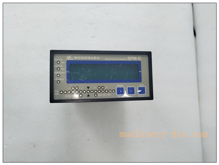
Woodward SPM-D11 (8440-2165) is a microprocessor-based generator synchronizer & power management controller
Product Title & Description
Model: SPM-D11, Part No: 8440-2165 The Woodward SPM-D11 (8440-2165) is a microprocessor-based generator synchronizer & power management controller, also widely known as SPM-D2-11 variant. It executes automatic paralleling, active/reactive load sharing, power factor control and generator protection for single or three-phase gensets. It is commonly deployed in power plants, combined cycle stations, marine power systems, industrial microgrids and critical backup power stations, coordinating generator speed and voltage to achieve bumpless breaker closing and balanced load distribution among multiple generators.
Core Product Overview
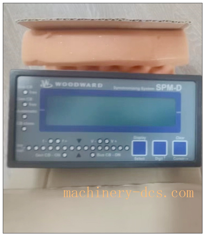
SPM-D11 is a panel-mounted synchronizing controller from Woodward SPM-D series. It continuously measures generator voltage/frequency/phase against busbar voltage, automatically sends speed bias and voltage bias signals to generator governor and AVR to match frequency, phase angle and voltage before closing the paralleling breaker. After synchronization, it controls active power and reactive power load sharing between paralleled generators, stabilizes power factor. It integrates generator protection functions: overvoltage, undervoltage, over/under frequency, phase loss and breaker failure detection. Front LCD display + LED synchroscope enables local visualization and commissioning. Configuration can be done via front panel or Woodward ToolKit software over USB. It can work with Woodward or third-party governors and automatic voltage regulators, widely used for diesel, gas engine and gas turbine generator sets.
SPM-D11 8440-2165
Main Technical Specifications
- Manufacturer: Woodward (USA)
- Part Number: 8440-2165
- Model: SPM-D11 (SPM-D2-11)
- Product Type: Generator Synchronizer & Load Share Controller
- Voltage Input: 100VAC (PT secondary), CT input /5A
- Frequency Range: 45 ~ 65 Hz
- Synchronization Accuracy: ±0.1Hz
- Power Supply: 100–240 VAC, 50/60Hz
- Control Output: 0–10VDC analog bias for speed & voltage adjustment; discrete relay outputs
- Load Sharing: Dual analog lines for active + reactive power sharing
- Display: 2-line LCD + LED synchroscope
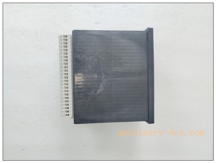
- Mounting: Panel cutout mounting
- Operating Temperature: -20°C ~ +60°C
- Storage Temperature: -40°C ~ +85°C
- Relative Humidity: 5–95%, non-condensing
- Weight: approx 1.0 kg
- Certifications: CE, UL
- Communication: USB for PC configuration; discrete I/O for mode & interlock
Quality Control Procedures
Woodward generator controls comply with ISO9001 and IEC power generation standards.
- Component incoming inspection: CPU, sampling circuits, relay, LCD and power components screened from approved suppliers.
- Automated assembly & serial traceability: SMT assembly, each unit with unique serial number for full lifecycle traceability.
- Full functional calibration test: Voltage/frequency sampling calibration, synchronizing simulation, load share test, relay protection and USB configuration verification.
- Environmental stress screening: Thermal cycling, vibration, surge and EMC testing for power control cabinet environment validation.
- Final inspection & packing: Visual inspection, anti-static packaging, factory test certificate supplied before shipment.
SPM-D11 8440-2165
Brand Related Model Recommendations
- 8440-1666 SPM-D11: Older synchronizer version, drop-in compatible for retrofit.
- SPM-D2-1115B/LSXR: Alternative code of 8440-2165.
- 505/505E: Woodward turbine digital governor, paired with for genset control.
- 2301A: Classic analog load sharing controller, legacy replacement candidate for .
Frequently Asked Questions (FAQ)
Q1: What is 8440-2165 used for? A1: Generator automatic synchronizing, paralleling breaker control, active/reactive load sharing and generator protection for multiple paralleled gensets.
Q2: Can it control both speed and voltage for synchronization? A2: Yes. It outputs speed bias signal to governor and voltage bias signal to AVR to match frequency, phase and voltage before paralleling.
Q3: How to program the controller? A3: Two ways: local keypad & LCD on front panel, or Woodward ToolKit software via USB connection from PC.
Q4: Is it suitable for gas turbine generator? A4: Yes. It supports fast-response gas turbine and slower diesel/gas engine prime movers.
Q5: What is the warranty for original Woodward 8440-2165? A5: Original Woodward unit carries standard 12-month factory warranty against manufacturing defects under proper installation and operation.
Installation & Configuration Guide
7.1 Pre-installation Preparation
Verify 8440-2165 , inspect front display, keypad and terminal block for damage. Prepare panel cutout, PT/CT wiring, shielded voltage/current cables, 100~240VAC auxiliary power, breaker control wiring and Woodward ToolKit software. Isolate generator and bus PT/CT circuits before wiring; observe high voltage safety rules. Wear ESD protection.
7.2 Installation Steps
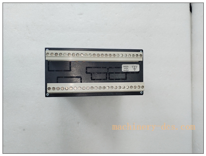
Cut cabinet panel to fit , secure unit into panel mounting frame. Connect PT voltage signals (Gen & Bus), CT current inputs, auxiliary AC power. Wire analog bias outputs to governor and AVR. Wire relay outputs to generator breaker control and alarm interlock circuits. Route shielded instrument cables with single-point grounding at control cabinet side. Tighten terminals, verify CT secondary short-circuit protection to avoid CT open circuit hazard.
7.3 System Configuration & Commissioning
Connect PC via USB, launch Woodward ToolKit. Set generator rated parameters, PT/CT ratios, synchronizing window thresholds, load sharing gains and protection setpoints. Download parameters to controller. Use front synchroscope to check voltage and phase measurement. Perform dry test (breaker open) to verify automatic frequency/voltage trimming. Execute no-load synchronization test, then on-load test to validate active/reactive load sharing. Save parameter backup and commissioning logs.
7.4 Maintenance & Precautions
During generator outages, inspect wiring terminals, cable shielding and front display status. Verify PT/CT circuit integrity. Do not open controller housing. If synchronization failure or unstable load sharing occurs, check PT/CT wiring, governor/AVR response and parameter settings before replacing . CT secondary must never be open when energized, which can cause dangerous high voltage.

 Start Chat


 Send an Email


