
Description
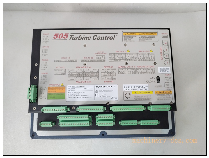
Woodward 8200‑1302 (505D) Digital Turbine Governor Controller with Integrated HMI
Product Brand & Model Title
Official Product Title: Woodward 8200‑1302 (505D) Digital Turbine Governor Controller with Integrated HMI
Brand: Woodward (USA)
Model: 8200‑1302
Product Series: 505D Turbine Control Series
Country of Origin: United States
8200-1302
Product Core Overview
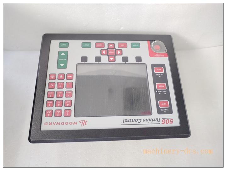
The Woodward 8200‑1302 is a high‑performance digital governor controller designed for steam turbine, gas turbine and prime‑mover speed‑load regulation, integrating an 8.4‑inch graphical HMI panel for local operation, monitoring and parameter configuration. It implements closed‑loop PID speed & load control, auto‑start sequence management, critical‑speed avoidance, overspeed protection, alarm and trip logic with RTC time‑stamped event logging.
Equipped with abundant configurable I/O channels and multi‑protocol communication interfaces, this unit can connect speed pickups, process transmitters, field sensors and DCS/SCADA host systems. It complies with ATEX hazardous‑area requirements and IACS UR E10 marine standard, suitable for power‑generation, petrochemical and offshore marine environments with harsh temperature, vibration and EMC conditions. It acts as a core standalone turbine control unit for new‑build and retrofit turbine control projects.
Main Technical Specifications
| Parameter | Specification |
|---|---|
| Manufacturer | Woodward |
| Model | 8200‑1302 (505D) |
| Device Type | Digital Turbine Governor Controller |
| Power Supply | 18‑36 VDC isolated DC supply (typical 24 VDC) |
| HMI Display | 8.4‑inch LCD graphical display with keypad & emergency stop button |
| Speed Input | 2 redundant speed inputs (magnetic pickup / proximity probe) |
| Analog Inputs | 8 configurable AI channels, supports 4‑20 mA / 0‑10 V, 27‑function configurable |
| Digital Inputs | 20 contact digital inputs (alarm, trip, function commands) |
| Analog Outputs | 2 × 4‑20 mA control outputs |
| Relay Outputs | 8 Form‑C relay outputs for alarm & trip interlock |
| Communication | Modbus‑TCP Ethernet, Modbus‑RTU RS‑485, RS‑232 service port |
| Control Performance | Steady‑state speed regulation ±0.02 %; dynamic ±0.05 % |
| Operating Temperature | ‑30 ℃ ~ +70 ℃; marine certified‑20 ℃ ~ +65 ℃ |
| Storage Temperature | ‑40 ℃ ~ +85 ℃ |
| Enclosure Rating | Front‑panel IP54; Pollution Degree 3 |
| Certifications | ATEX, IACS UR E10 Marine, EN 61000‑6‑2 EMC |
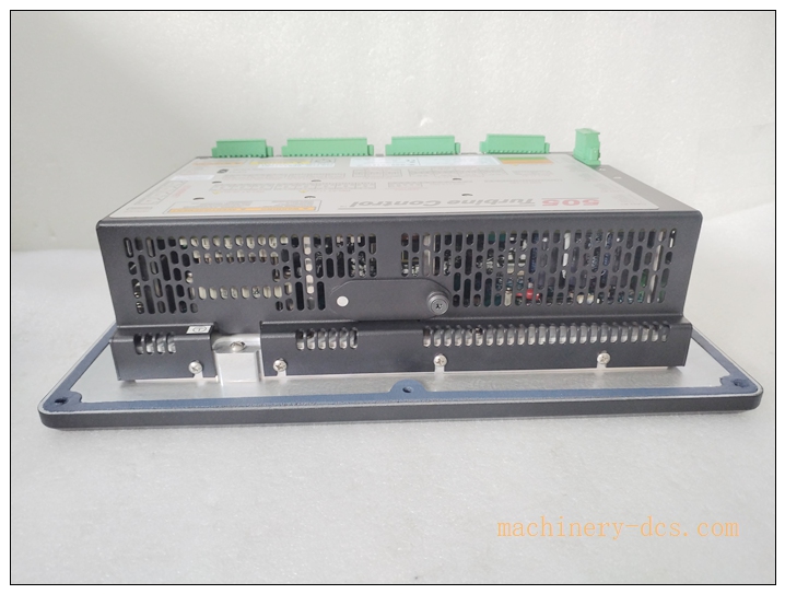
| Weight | 1.8 kg |
| Mounting | Panel cut‑out mounting |
| Warranty | 12‑month manufacturer warranty |
Woodward 505D / Related Series Recommended Models (6+)
- 8200‑1302: 505D full‑feature panel‑mount turbine governor with integrated 8.4‑inch HMI (reference main model)
- 8200‑1301: 505D basic governor, without local HMI, for cabinet‑mount remote‑HMI deployment
- 8200‑1303: 505D enhanced version with extended safety trip logic for high‑risk steam turbine applications
- 8200‑1304: 505D marine‑optimized variant, reinforced conformal coating for offshore salt‑fog environment
- 8200‑1305: 505D redundant CPU hot‑standby control unit for SIL‑adjacent turbine protection systems
- 8200‑1306: Remote HMI display panel, works with headless 505D controllers for control‑room local operation
- 8200‑1307: Expansion I/O module for 505D series, increasing analog & digital channels for complex turbine auxiliary monitoring
Professional Quality Control & Test Standard Operating Procedure (SOP)
- Incoming Component Verification Verify main CPU board, I/O circuit boards, HMI display unit, relay assemblies and connectors comply with Woodward component specifications. Reject non‑conforming electronic components before assembly.
- PCB Assembly & Bench Functional Test After SMT assembly, perform channel‑by‑channel simulation test. Inject simulated speed‑pickup signals, 4‑20 mA analog signals and dry‑contact digital signals. Verify I/O accuracy, relay switching action and HMI display rendering.
- Thermal Burn‑in Aging Test 72‑hour continuous powered aging at 60 ℃ ambient temperature. Monitor CPU operating status, communication stability, I/O drift and temperature rise to screen early‑failure hardware defects.
- Environmental Compliance Test Carry out temperature cycling, vibration shock and EMC EMI/EMS testing following IEC 61000 and IEC 60068 standards. Validate performance under industrial and marine harsh‑condition simulation.
- Full‑Function Control Logic Validation Test core governor functions: auto‑start sequence, critical‑speed avoidance, overspeed trip, load‑droop control, alarm & trip event logging with RTC timestamp. Verify Modbus‑TCP / Modbus‑RTU communication data exchange.
- Final Calibration & Batch Sampling Inspection Calibrate speed‑input scaling, analog‑input/output range and relay threshold parameters. 5 % random sampling retest for each production batch. Generate traceable factory test reports before labelling and shipment.
8200-1302
New Module Installation Guidelines
6.1 Pre‑installation Preparation
Cut off all related power sources. Confirm cabinet power supply meets 18‑36 VDC isolated specification. Inspect 8200‑1302 for mechanical damage, connector deformation and screen scratch. Prepare panel‑mount accessories, shielded sensor cables, shielded Ethernet cable and insulated screwdrivers. Observe anti‑static protection requirements.
6.2 Hardware Panel‑mount Installation
Install the controller into the standard cabinet panel cut‑out. Fasten mounting clamps evenly to fix the unit. Route field cables separately: keep speed‑pickup and analog signal cables away from high‑power cables to reduce EMI interference. Connect DC power supply, speed sensors, analog transmitters, digital input dry contacts and relay output wiring strictly per official wiring diagram. Tighten terminal screws properly.
6.3 Software Configuration & Commissioning
Power on the unit. Enter configuration mode via local HMI or Woodward configuration tool via RS‑232 service port. Set turbine parameters: speed range, critical‑speed bands, PID gain parameters, alarm & trip thresholds, I/O function assignment, communication IP address and Modbus register mapping. Perform simulated speed test to verify governor response, alarm trigger and trip action. Save configuration files locally and backup offline copies.
6.4 Post‑installation Validation
Check HMI status indicators and real‑time process values. Conduct 4‑hour continuous running test. Verify event‑logging function, DCS communication data consistency. Confirm no false alarms, abnormal heating or communication dropout. Complete commissioning acceptance.
Application Scenarios & Product Features
Application Scenarios
- Steam turbine & gas turbine speed‑load control for power‑generation plants
- Turbo‑generator prime‑mover governing and safety trip monitoring
- Petrochemical process plant turbine drive equipment
- Marine & offshore platform turbine / engine governing systems
- Industrial combined‑cycle unit control retrofitting projects
- DCS‑connected turbine control for central‑monitoring automation systems
Core Features
- Integrated 8.4‑inch graphical HMI for local parameter viewing, adjustment and event review
- Redundant dual‑channel speed‑input for anti‑failure speed‑measurement safety
- Built‑in auto‑start sequence, critical‑speed avoidance, overspeed protection and timestamped event log
- Rich configurable I/O resources to adapt to various turbine auxiliary signal requirements
- Multi‑protocol communication (Modbus‑TCP / Modbus‑RTU) for seamless DCS/SCADA integration
- ATEX hazardous‑area and IACS UR E10 marine certification for harsh industrial & offshore environments
- Configurable PID speed‑load algorithm for stable dynamic response under variable working conditions
- Complete alarm‑trip management for equipment fault early warning and safety interlock protection
Frequently Asked Questions (FAQ)
Q1: HMI screen no display after power‑on
A1: Verify DC power supply voltage stays within 18‑36 VDC rated range. Check power‑terminal wiring tightness and polarity. Check internal power fuse status. Perform full power‑cycle reset. If fault persists, return for hardware inspection.
Q2: Speed reading shows zero or unstable speed signal
A2: Inspect speed‑pickup sensor installation gap and cable integrity. Check speed‑input channel configuration (sensor type, gain setting). Check cable shielding grounding; separate sensor wiring from high‑voltage power cables. Replace speed‑pickup unit for fault isolation.
Q3: Governor cannot maintain stable rotating speed under load variation
A3: Review PID proportional‑integral‑derivative parameters; retune PID gains for actual turbine characteristics. Check actuator feedback signal and valve mechanical friction. Verify no wrong‑configured limiting parameters. Re‑perform commissioning calibration.
Q4: Cannot establish Modbus‑TCP communication with upper‑level DCS
A4: Confirm IP‑address setting matches host network segment; exclude IP‑address conflict. Verify Modbus register mapping configuration. Check Ethernet cable and switch port status. Restart controller and re‑establish network connection.
Q5: Unexpected trip event occurs during operation
A5: Check HMI event log for timestamped trip root‑cause information. Verify hardware‑trip input channel status, overspeed threshold and process‑interlock conditions. Check field‑sensor signal abnormal fluctuation. Eliminate field‑side trigger source before resetting trip.
Q6: What regular maintenance is required for 8200‑1302?
A6: Every 3‑6 months, check terminal‑screw tightness and cabinet ventilation; remove dust accumulation. Regularly backup controller configuration files. Avoid continuous over‑temperature operation. Do not clean circuit‑board parts with liquid solvents. Check HMI keypad physical condition periodically.

 Start Chat


 Send an Email


