
Description
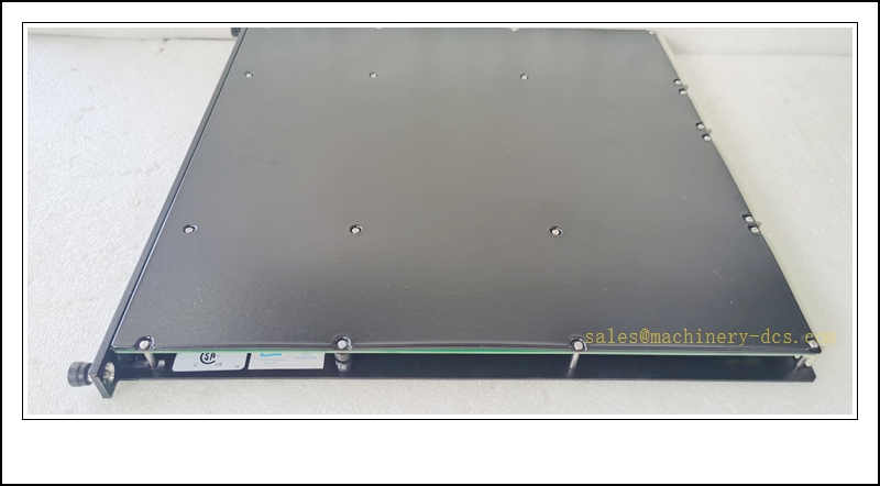
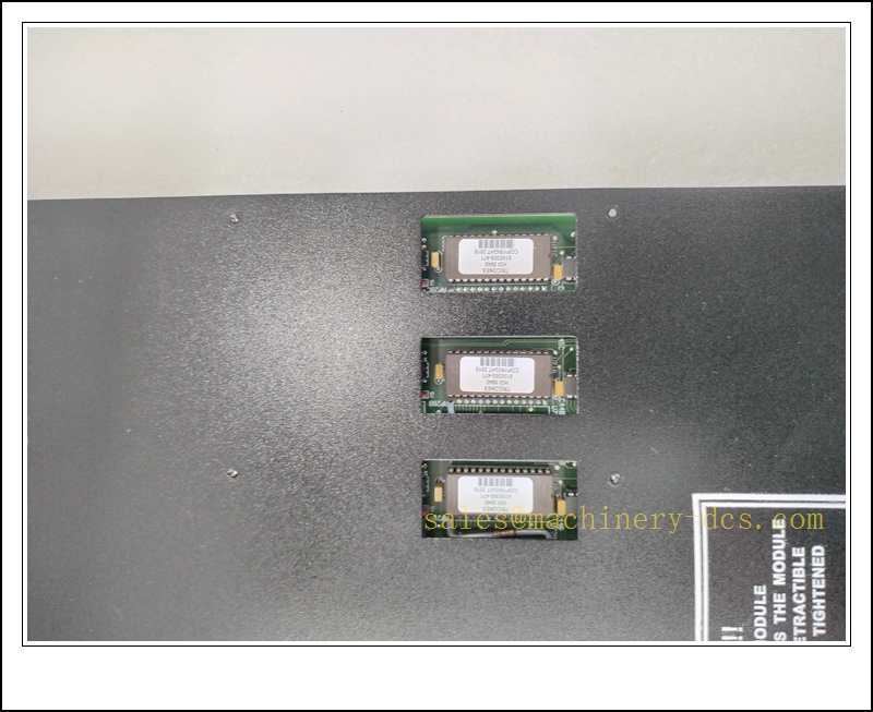
Triconex 3503E Digital Input Module, TMR 24VDC SIS DI Module
Product Description
The Triconex 3503E is a triple modular redundant digital input module designed for the Tricon Safety Instrumented System (SIS). It acquires 24 VDC discrete field signals from emergency shutdown pushbuttons, pressure switches, level switches, fire and gas detectors, and other safety contact devices, and transmits validated status data to the Tricon main processor triplet via the Tricon backplane bus. The module implements independent 2oo3 voting across three isolated signal paths to tolerate single-channel hardware faults without disrupting safety function execution. Built-in diagnostics detect open circuit, short circuit, and internal leg failures; fault status is reported to TriStation for alarm and maintenance management. It supports hot-swap replacement when deployed within a healthy Tricon rack, allowing online maintenance without taking the safety system offline. The module mates with dedicated terminal assemblies for field wiring termination.
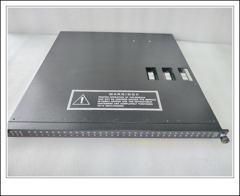
TRICONEX 3503E
Technical Specifications
- Brand: Triconex (Schneider Electric / Invensys Legacy)
- Model: 3503E
- Module Type: Digital Input (DI) Module
- Architecture: TMR Triple Modular Redundancy, 2oo3 voting
- Channel Count: 32 channels, commoned return
- Nominal Field Input: 24 VDC
- Operating Input Voltage Range: 15 VDC ~ 30 VDC
- Input Impedance: Approximately 3 kΩ
- Filter Response Time: <10 ms
- Diagnostics: Wire break detection, short-circuit detection, leg fault, module self-test
- Backplane Interface: Tricon dedicated I/O bus
- Hot Swap: Supported with a healthy Tricon rack and valid processor triplet
- Operating Temperature: 0 °C to +60 °C
- Storage Temperature: -40 °C to +85 °C
- Relative Humidity: 5%–95%, non-condensing
- Safety Certification: SIL 3 capable per IEC 61508, ATEX Zone 2, UL, CE
- Compatibility: Tricon 7-slot /15-slot main and expansion chassis
- Power Source: Powered via Tricon chassis backplane
Application Scenarios
- Petrochemical and refinery ESD emergency shutdown safety contact monitoring
- Onshore and offshore oil & gas fire and gas detection system input acquisition
- Power plant boiler protection, turbine trip and burner management safety switches
- LNG terminal and cryogenic plant SIL 3 safety instrumented discrete signal monitoring
- Unmanned pipeline pressure and flow safety switch cabinets
- Chemical plant safety interlock discrete input monitoring
- Hazardous Class I Div 2 / Zone 2 SIS control panels
- Spare part replacement and maintenance for existing Tricon SIS installations
8 Related Triconex Model Recommendations
- 3504E – Tricon 32-Channel Digital Output Module
- 3805E – Tricon Main Processor Module
- 3703E – 8-Channel Analog Input Module
- 3704E – 8-Channel Analog Output Module
- 4351B – Tricon Communication Module TCM
- 8310 – 120VAC/VDC Tricon Power Supply
- 8311 – 24VDC Tricon Power Supply
- 3721 – Tricon Communication Interface Module
Compatibility & Installation Pitfalls
Compatibility
- Designed exclusively for Tricon TMR chassis; not compatible with Trident racks or Bently Nevada 3500 racks.
- Requires Tricon main processor triplet (3805E series) and matching chassis firmware revision.
- It is a commoned-return DI module; cannot be substituted for isolated input types.
- Application logic and I/O configuration reside in the Tricon main processor, not locally on the 3503E. Module replacement requires validated application download if necessary.
- SIL 3 safety integrity depends on healthy TMR processor triplet and proper fault detection configuration.
- Must be paired with the correct Tricon terminal assembly; incompatible termination units lead to wiring and diagnostic failures.
Installation Pitfalls
- Hot-swap is permitted only when the Tricon rack is fully online with all three processors in PASS status. Do not perform hot-swap during active safety trips or processor faults.
- This is a commoned return design; incorrect shared return wiring will introduce crosstalk and false switch status changes.
- 24 VDC field wiring must be routed separately from high-power VFD and AC cables to avoid electromagnetic interference causing spurious input triggers.
- Onboard diagnostics detect wire breaks and shorts, but cannot verify mechanical degradation of field switches; periodic proof-test of field devices remains mandatory.
- Do not apply voltage outside the 15–30 VDC range; overvoltage can permanently damage input channels.
- Mechanical keying prevents insertion into non-I/O slots; never force the module into processor, power or communication slots.
- Verify field circuit polarity at the terminal assembly; reversed polarity may impair wire-break diagnostic functionality.
- Firmware mismatch between the 3503E and the Tricon processor triplet can disable channel diagnostics and TMR voting functions.
Standard Operating Procedure (SOP)
SOP for 3503E Digital Input Module Inspection, Installation and Functional Test
- Pre-Installation Inspection Inspect the module for physical damage, bent connectors or contamination. Confirm the part number 3503E. Verify matching terminal assembly and Tricon firmware compatibility. Review field switch drawings and commoned return design. Apply lockout-tagout to associated safety input circuits if the module supports critical ESD functions.
- Rack Installation Power down the chassis if replacing the only active module for a critical safety loop. Insert the 3503E into the designated I/O slot and secure module fasteners. Connect the ribbon cable between the module and field terminal assembly. Terminate 24 VDC field contact wiring at terminals. Separate discrete field wiring from high-energy power cables and apply shielding per approved SIS documentation.
- Software Configuration Open TriStation and connect to the Tricon rack. Add and map the 3503E within the system I/O configuration. Enable wire-break diagnostics as required by the SIL safety requirements specification. Download the validated safety application to the 3805E processor triplet and resolve firmware or configuration mismatch alarms. Archive the I/O configuration for IEC 61508 audit traceability.
- Channel and Diagnostic Test Actuate each field switch and confirm the input status updates correctly within TriStation. Simulate open-circuit and short-circuit conditions to validate diagnostic alarm reporting. Confirm TMR voting suppresses single leg faults without generating false trip signals. Record channel response and diagnostic performance in the SIS maintenance log.
- System-Wide Interlock Verification Trigger safety input trip conditions and confirm the Tricon executes the required shutdown sequence. Confirm single module/leg faults only raise maintenance alarms and do not cause undesired ESD activation. Verify interlock status propagates correctly to HMI and peer systems.
- Return to Service Clear temporary fault latches and alarm acknowledgements. Remove lockout-tagout as applicable. Monitor channel health and fault status through the required observation period. Notify operations that the Tricon digital input module is in service.
- Periodic Maintenance and Replacement During planned outages, inspect terminal torque, cable insulation and field switch condition. Perform full channel proof-test and wire-break diagnostic testing per site SIS schedule. If the 3503E reports persistent non-resettable leg faults, confirm the Tricon processor triplet is fully healthy before hot-swap. After replacement, recheck all channels and diagnostics before releasing the module to safety duty.

 Start Chat


 Send an Email


