
Description
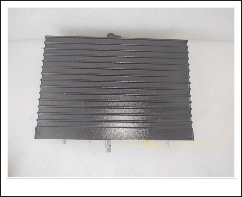
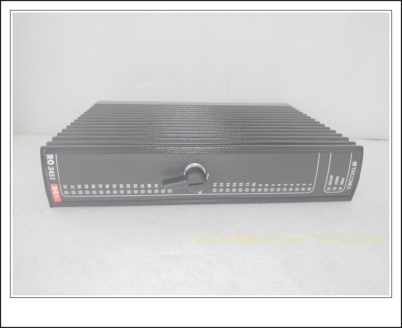
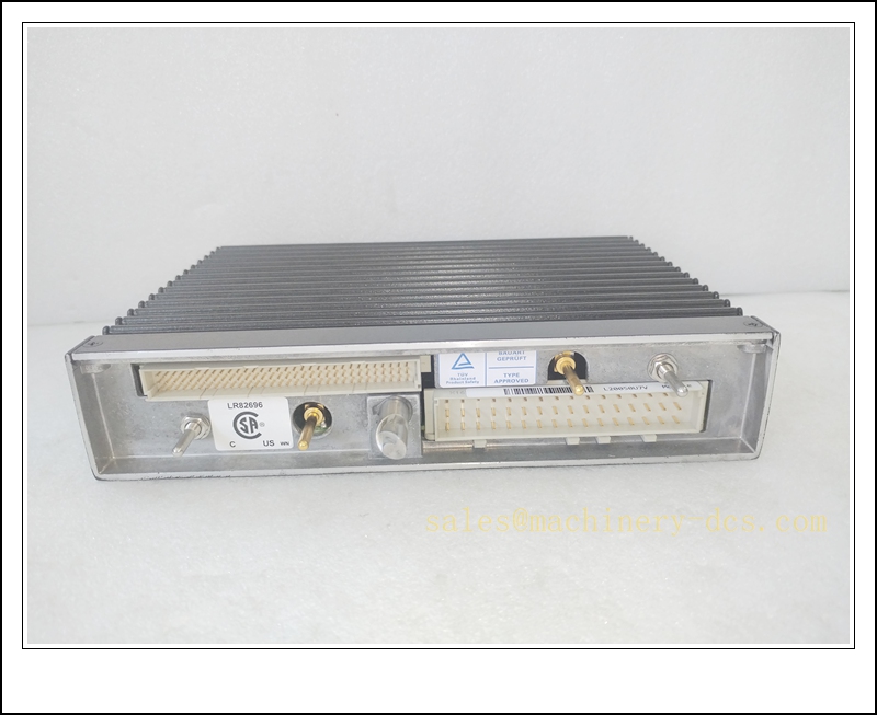
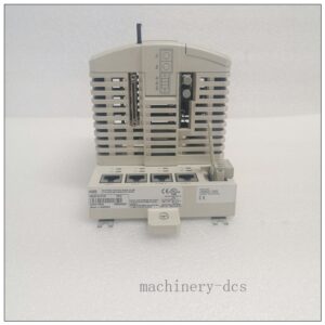
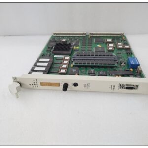
Triconex 3451 8-Channel TMR Analog Input Module for Trident SIS, SIL 3 Rated
Product Description
The Triconex 3451 is a triple modular redundant (TMR) analog input module built exclusively for the Triconex Trident safety instrumented system. It acquires 4–20 mA analog signals from field transmitters such as pressure, temperature, flow and level sensors, and transmits validated digital process values to the 3101 Trident main processor triplet over the Trident I/O bus. It adopts a 2oo3 mid-value voting strategy across three independent signal acquisition channels to tolerate single hardware faults without interrupting safety monitoring functions. Integrated diagnostics detect over-range, under-range, open circuit, short circuit and internal leg failures, and fault information is reported to the processor and TriStation 1131 software for alarm management and maintenance. Hot-swap capability supports online replacement while the Trident rack remains operational, minimizing downtime for continuous process plants. This module requires a dedicated Trident baseplate and matched external termination assembly for field wiring.
TRICONEX 3451
Technical Specifications
- Brand: Triconex (Schneider Electric / Invensys Legacy)
- Model: 3451
- Module Type: Analog Input (AI)
- Architecture: TMR Triple Modular Redundancy, 2oo3 mid-value voting
- Channel Count: 8 analog input channels
- Input Signal: 4–20 mA
- Resolution: 16-bit
- Typical Accuracy: ±0.1% full span
- Input Impedance: 250 Ω built-in
- Galvanic Isolation: Field-to-backplane isolation
- Diagnostics: Over-range, under-range, open circuit, short circuit, module self-test, leg fault detection
- Backplane Interface: Trident dedicated I/O bus
- Hot Swap: Supported when Trident rack is online with all three main processors healthy
- Operating Temperature: 0 °C to +60 °C
- Storage Temperature: -40 °C to +85 °C
- Relative Humidity: 5% to 95%, non-condensing
- Safety Certification: SIL 3 capable per IEC 61508
- Configuration Software: TriStation 1131 (Trident platform only)
- Power Supply: Powered via Trident baseplate backplane
Application Scenarios
- Legacy petrochemical and refinery ESD analog measurement loops
- Onshore and offshore oil & gas Trident SIS transmitter signal acquisition
- Power plant boiler and turbine safety-related process monitoring
- Burner Management System (BMS) analog measurement for Trident racks
- LNG and cryogenic plant safety instrumented analog input monitoring
- Chemical continuous process safety pressure, temperature and level measurement
- Hazardous Class I Div 2 / Zone 2 SIS cabinets based on Trident platform
- Spare part replacement and outage maintenance for existing Trident installations
8 Related Triconex Model Recommendations
- 3101 – Trident Main Processor Module
- 3102 – Trident Redundant Communication Module
- 3301 – Trident 32-Channel Commoned Digital Input Module
- 3302 – Trident Digital Output Module
- 3401 – Trident 8-Channel Analog Output Module
- 3501 – Trident Chassis and Backplane Assembly
- 4000098-510 – Tricon / Trident Redundant Power Supply
- 3805E – Tricon Main Processor (Modern Migration Platform)
Compatibility & Installation Pitfalls
Compatibility
- Designed exclusively for the Trident chassis and Trident backplane; not compatible with Tricon 3700/3600 series racks.
- Configured only via TriStation 1131; modern Tricon TriStation software cannot communicate with Trident hardware.
- Requires dedicated Trident baseplate and matching termination assembly; Tricon ETPs are not pin-compatible.
- Application logic and I/O configuration reside in the 3101 main processor, not locally on the 3451. Module replacement requires downloading the validated Trident application.
- SIL 3 safety integrity depends on a fully healthy TMR processor triplet; a standalone 3451 cannot achieve SIL 3.
- Firmware revision must match the 3101 processors and other Trident I/O modules to retain safety certification.
Installation Pitfalls
- Hot-swap is permitted only when all three Trident main processors are in PASS state. Do not hot-swap during processor faults or active safety trips.
- The module integrates 250 Ω internal shunt resistors for 4–20 mA; adding external extra shunts will distort current readings.
- Analog field cables must be separated from high-voltage AC and VFD power cables; electromagnetic interference causes signal drift and spurious alarms.
- Ground potential differences between the SIS cabinet and field transmitters create ground loops and unstable mA measurements; follow single-point shielding rules.
- Onboard diagnostics detect electrical faults such as wire breaks and shorts, but cannot identify transmitter calibration drift or sensor degradation; periodic proof-test is mandatory.
- Mechanical keying prevents insertion into the wrong baseplate; never force the module into an incompatible slot, which may damage backplane connectors.
- Do not apply voltage signals directly to the 4–20 mA current channels; incorrect signal types lead to channel damage.
- Mismatched firmware versions between the 3451 and processor triplet can disrupt voting and diagnostic functions, invalidating SIL integrity.
TRICONEX 3451
Standard Operating Procedure (SOP)
SOP for 3451 Analog Input Module Inspection, Installation and Functional Test
- Pre-Installation Inspection Inspect the module for physical damage, bent connector pins or contamination. Confirm the part number is 3451 for the Trident platform. Verify the matching baseplate and termination assembly. Review field transmitter specifications and safety trip logic. Apply lockout-tagout to associated ESD safety loops before rack access.
- Rack Installation Power down the Trident chassis if the module supports a critical safety loop without redundant I/O path. Insert the 3451 into the designated Trident I/O baseplate and secure the locking latch. Connect the ribbon cable from the module rear connector to the external termination assembly. Terminate 4–20 mA field transmitter wiring on the terminal base. Separate low-level analog wiring from high-energy power cables and apply shielding per approved SIS drawings.
- Software Configuration Launch TriStation 1131 and upload the validated Trident application. Map the 3451 in the I/O configuration table. Configure engineering units, high/low alarm and trip thresholds, and enable range diagnostics per the SIL safety plan. Download the application to the 3101 processor triplet and resolve configuration or firmware mismatch faults. Archive the compiled application for IEC 61508 audit traceability.
- Channel Calibration and Signal Injection Test Isolate field transmitters as required. Inject 4 mA, 12 mA and 20 mA reference signals to each channel. Verify readings in TriStation 1131 fall within the specified accuracy tolerance. Simulate open circuit and short-circuit conditions to confirm fault reporting. Confirm over-range and under-range signals trigger configured diagnostic alarms.
- Safety Interlock Functional Verification Reconnect field transmitters. Inject trip setpoint signals and confirm the Trident executes the designed shutdown sequence. Verify TMR voting rejects single leg faults and prevents spurious trips. Record calibration accuracy, diagnostic response and trip behaviour in the SIS proof-test log.
- Return to Service Clear all temporary test forces and diagnostic latches. Remove lockout tags and restore the safety monitoring loop to online status. Monitor module health and analog channel stability for the required observation period. Notify operations that Trident analog safety measurement is active.
- Periodic Maintenance and Replacement During planned outages, inspect baseplate terminal torque, cable shielding and transmitter loop integrity. Repeat signal injection calibration and range diagnostic tests per the site SIS proof-test schedule. If the 3451 reports persistent unrecoverable leg faults, confirm the three main processors are healthy before hot-swap. After installing a replacement module, confirm synchronization with the Trident processor triplet, reload validated I/O configuration and run full calibration and interlock test before releasing the module to safety duty.

 Start Chat


 Send an Email


