
Description
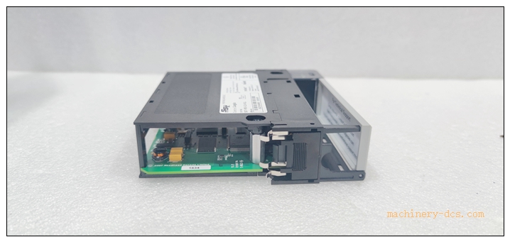
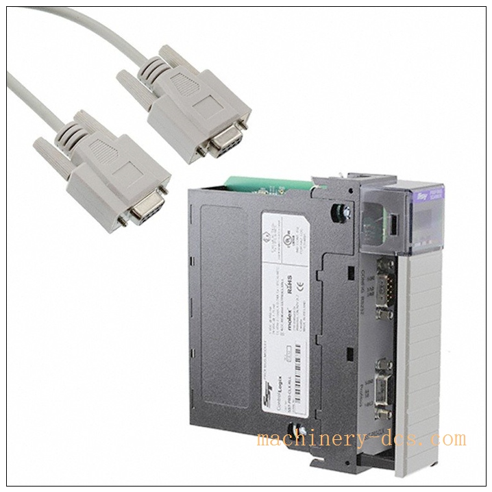
SST‑PB3‑CLX‑RLL PROFIBUS‑DP Scanner Module for ControlLogix
Brand: MOLEX (Woodhead / SST)
Model: SST‑PB3‑CLX‑RLL
Product Series: SST‑PB3 ControlLogix Communication Module Series
Country of Origin: United States
Product Type: 1756‑Chassis Slot‑mount PROFIBUS‑DP Master/Slave Communication ModulePROFIBUS &…
Product Core Overview
The SST‑PB3‑CLX‑RLL is an in‑chassis fieldbus communication module designed for Rockwell Automation ControlLogix (1756) PLC platform. It works as PROFIBUS‑DP‑V0 / DP‑V1 scanner (master) or DP slave, bridging ControlLogix backplane and PROFIBUS‑DP field network.
With independent onboard processor and flash memory, the module handles full PROFIBUS protocol stack locally without burdening the ControlLogix CPU. It exchanges cyclic I/O data, acyclic DP‑V1 parameter access and comprehensive diagnostic information between Logix controller and PROFIBUS‑DP slaves (drives, remote I/O, transmitters). The RLL suffix includes RSLogix‑5000 Add‑On‑Profile for seamless integration into Studio 5000 / RSLogix 5000 environmentPROFIBUS &…. Widely used for factory‑automation retrofits, migration projects connecting Rockwell systems to European‑origin PROFIBUS field devices.
SST‑PB3‑CLX‑RLL
Main Technical Specifications
| Parameter | Specification |
|---|---|
| Manufacturer | MOLEX Woodhead‑SST |
| Model | SST‑PB3‑CLX‑RLL |
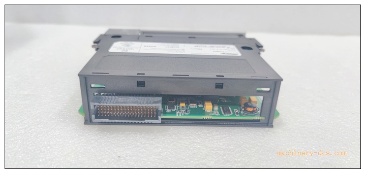
| Compatible Chassis | Allen‑Bradley ControlLogix 1756 series backplane |
| Slot Requirement | Single slot |
| Backplane Current | 850 mA @ 5 VDC; 1.75 mA @24 VDC |
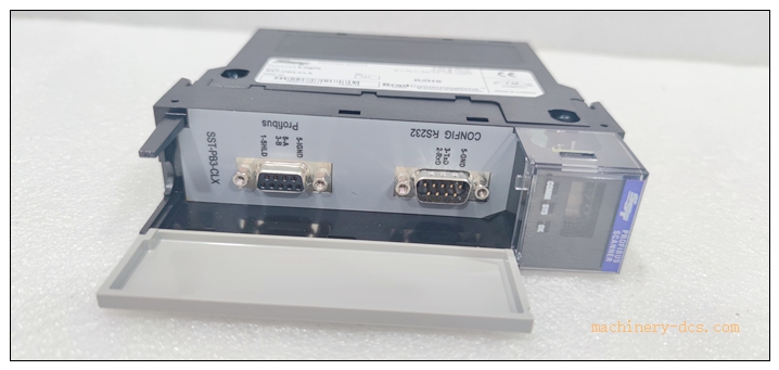
| PROFIBUS Interface | 9‑pin D‑Sub female, RS‑485, galvanic isolation 500 V DC |
| Supported Protocol | PROFIBUS‑DP‑V0 Class 1/2; DP‑V1 Class 1/2; Master / Slave / Mixed modePROFIBUS &… |
| Baud Rate | 9.6 Kbps ~ 12 Mbps standard PROFIBUS rates |
| Max DP Slaves (Master) | Up to 125 nodes |
| Max I/O Data | 1984 input bytes; 1968 output bytes total |
| On‑board Memory | 512 KB shared memory; 512 KB flash for configuration & firmware |
| Local Interface | USB 2.0 Type‑A for firmware upgrade & configuration download |
| Status Indicators | OK, SYS, COMM LED indicators, 4‑character scrolling status display |
| Operating Temperature | 0 °C ~ +60 °C |
| Storage Temperature | −40 °C ~ +85 °C |
| Enclosure Rating | IP20 (cabinet‑only installation) |
| Weight | 0.24 kg |
| Certifications | CE, UL listed |
| Warranty | 12‑month manufacturer warranty |
Note: Module does not integrate onboard PROFIBUS terminator; external bus terminator must be fitted at physical bus end‑point.
SST‑PB3 Series Related Models
- SST‑PB3‑CLX‑RLL: Standard PROFIBUS‑DP scanner with RLL Add‑On‑Profile (reference model)
- SST‑PB3‑CLX‑RLL‑CC: Conformal‑coated version for high‑humidity / corrosive cabinet environmentPROFIBUS &…
- SST‑PB3‑CLX‑DTM: Equipped with DTM driver license for FDT frame software
- SST‑PFB‑CLX: Earlier‑generation SST PROFIBUS‑DP module for ControlLogix
- SST‑DNP‑CLX: DNP3 communication module for ControlLogix chassis
- SST‑MB‑CLX: Modbus RTU/TCP communication module for ControlLogix platform
Professional Quality Control & Test Standard Operating Procedure (SOP)
- Incoming Component Inspection Inspect main processor, memory chips, PROFIBUS transceiver, backplane connector, D‑Sub port. Verify components comply with MOLEX‑SST industrial grade specification; reject non‑conforming components before assembly.
- PCB Assembly & Bench Functional Test After SMT assembly, perform power‑on initialization test. Verify ControlLogix backplane handshake, USB port function, PROFIBUS physical‑layer signal quality. Simulate DP‑V0 cyclic data exchange and DP‑V1 acyclic read/write with virtual PROFIBUS slaves.
- Thermal Burn‑in Aging Test 72‑hour powered burn‑in test at 55 °C ambient temperature. Run cyclic PROFIBUS network simulation, continuous data refresh, stress‑test flash read‑write operations. Screen for early‑life hardware defects.
- Environmental Compliance Validation Temperature cycling, vibration‑shock and EMC EMI/EMS testing following IEC 61000‑6‑2 and IEC 60068 standards, simulating factory cabinet interference environment.
- Full‑System ControlLogix Rack Integration Test Insert SST‑PB3‑CLX‑RLL into 1756 chassis. Test backplane data mapping with Logix CPU, download AOP profile, import GSD files, build PROFIBUS project configuration. Verify cyclic I/O exchange, slave diagnostics, DP‑V1 parameter access, LED and character‑display status feedback.
- Final Calibration & Batch Sampling Release Firmware version validation; 5 % random‑sample retest per batch. Record serial number and firmware revision. Generate traceable factory‑test records prior to labelling and shipment.
SST-PB3-CLX-RLL
New Module Installation Guidelines
6.1 Pre‑installation Preparation
Power‑off the ControlLogix rack or confirm hot‑swap capability of chassis. Wear anti‑static wristband for ESD protection. Inspect SST‑PB3‑CLX‑RLL for mechanical damage, bent backplane pins or D‑Sub connector damage. Prepare shielded PROFIBUS cable, external bus terminator, USB configuration cable, Studio 5000 / RSLogix 5000 software and corresponding GSD files for field slaves.
6.2 Hardware Rack Installation
Slide module into free single slot of 1756 ControlLogix chassis, push firmly until backplane connector fully seated. Lock module front‑panel retainer. Connect PROFIBUS‑DP cable to D‑Sub 9‑pin port; install external terminator at physical bus end. Route PROFIBUS signal cable separately from high‑power AC cables to minimise EMI interference. Apply proper cable‑shield grounding according to PROFIBUS installation guideline.
6.3 System Configuration & Commissioning
Power‑on ControlLogix rack. Install module AOP (Add‑On‑Profile) within Studio 5000. Import GSD files for PROFIBUS‑DP slaves. Configure module operating mode (Master / Slave), baud‑rate, slave list, cyclic input/output data mapping, DP‑V1 parameters. Download configuration to module via backplane or USB interface. Bring PROFIBUS network online; verify each slave enters data‑exchange state. Save complete PLC project and module configuration files for offline backup.
6.4 Post‑installation Validation
Check front‑panel LED and 4‑character status display. Verify cyclic PROFIBUS I/O data consistency inside Logix tag database. Review module diagnostic counters (CRC errors, token errors, slave status). Run continuous 4‑hour runtime test. Confirm no communication drop‑outs, no unexpected slave drop‑off, complete commissioning acceptance.
Application Scenarios & Product Features
Application Scenarios
- Rockwell ControlLogix PLC connecting to PROFIBUS‑DP drives, remote I/O, field instruments
- Petrochemical, power, water‑treatment plant mixed‑vendor automation system integration
- Machine‑building industry retrofitting projects: migrate legacy PROFIBUS equipment into Logix platform
- Factory‑automation production‑line upgrade, connecting European‑origin PROFIBUS field devices
- Spare‑part replacement & system‑revamp for existing SST‑PB3‑CLX‑RLL installed base
Core Features
- Support PROFIBUS‑DP‑V0 / DP‑V1, configurable as Master, Slave or mixed Master+Slave modePROFIBUS &…
- Independent onboard processor, offloads PROFIBUS protocol processing from ControlLogix CPU
- Large‑volume cyclic I/O data exchange capacity for complex PROFIBUS networks
- Comprehensive PROFIBUS‑DP diagnostic counters and slave status reporting
- Built‑in USB port for local firmware upgrade and configuration download
- Comes with RLL Add‑On‑Profile for native Studio 5000 / RSLogix 5000 integration
- 4‑character scrolling display plus multi‑LED status indication for quick‑on‑site troubleshooting
- Galvanic isolation between ControlLogix backplane and PROFIBUS‑DP field side
- Standard single‑slot ControlLogix chassis form‑factor for easy replacement
SST-PB3-CLX-RLL
Frequently Asked Questions (FAQ)
Q1: Module OK LED off after rack power‑on
A1: Check 5 VDC backplane power budget of 1756 chassis. Confirm module fully inserted and retainer locked. Verify firmware‑AOP version compatibility. Perform full rack power‑cycle. If fault persists return for hardware inspection.
Q2: PROFIBUS slaves cannot go into data‑exchange state
A2: Verify baud‑rate consistency across whole PROFIBUS segment. Check external bus terminator installation at bus physical endpoints. Inspect cable shielding grounding, D‑Sub connector pin integrity. Confirm GSD file matches actual slave hardware revision; review module diagnostic error counters.
Q3: Cyclic I/O data unstable, intermittent slave drop‑out
A3: Check PROFIBUS cable layout; separate signal wiring from high‑power cables. Inspect for poor D‑Sub connector contact, loose shield termination. Analyze CRC and token error diagnostic counters; identify interference sources on‑site.
Q4: Can SST‑PB3‑CLX‑RLL replace older SST‑PFB‑CLX directly?
A4: Physical form‑factor fits same 1756 slot, but firmware, AOP profile and configuration file format differ. Cannot reuse old PFB‑CLX configuration directly; requires re‑configuration and project modification.
Q5: DP‑V1 acyclic parameter read/write fails
A5: Confirm target slave supports DP‑V1 function. Verify module configuration enables DP‑V1 feature. Check slave address setting and GSD version. Review module diagnostic buffer for detailed DP‑V1 error codes.

 Start Chat


 Send an Email


