
Description
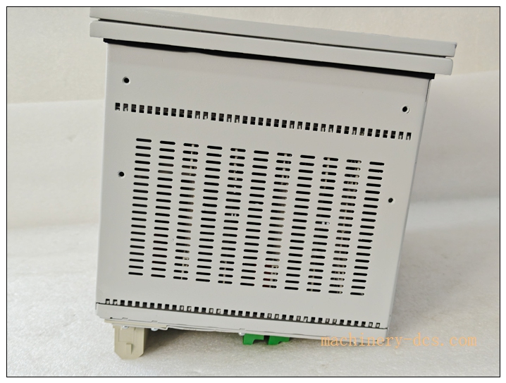
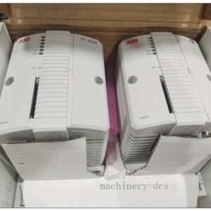
REM543 Machine Protection Terminal, Order‑code REM543CM216AAA
Brand: ABB Model: REM543CM216AAA
Product Series: REM54x series rotating‑machine protection relay
Country of Origin: Finland
Product Type: Panel‑mount machine protection & control IED
Status: Legacy, discontinued since 2022, spare‑part onlyABB Group
Product Core Overview
The REM543CM216AAA is a comprehensive machine‑protection intelligent electronic device (IED) for medium‑voltage motors and small‑to‑medium generators. It integrates full‑set protection algorithms, measurement, control, programmable logic, disturbance recording and multi‑protocol communication within one unitABB Group.
It covers short‑circuit, earth‑fault, overload, unbalance, stall, start‑up supervision, differential protection for rotating equipment. Equipped with rich binary I/O, RTD temperature monitoring support, fault waveform recording and event sequence logging. It supports SPA, Modbus‑RTU, IEC‑60870‑5‑103; IEC 61850 available via SPA‑ZC400 adapter. Widely applied in power plants, mining, marine‑off‑shore, heavy‑industry for motor/generator primary‑protection and retrofitting spare‑part replacement.
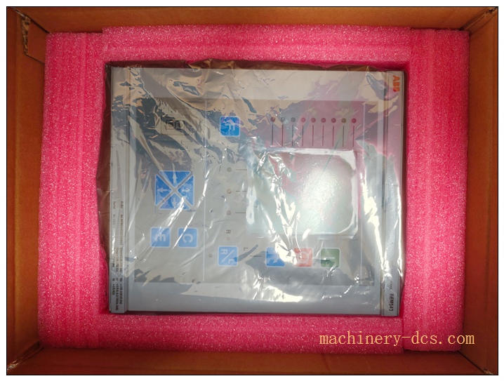
REM543CM216AAA
Main Technical Specifications
| Parameter | Specification |
|---|---|
| Manufacturer | ABB |
| Model | REM543CM216AAA |
| Auxiliary supply | 110‑240 V AC / 110‑220 V DC, 50/60 Hz |
| CT rated input | 1 A / 5 A selectable |
| VT rated input | 100‑120 V |
| Binary Inputs | 15 pcs opto‑isolated DI |
| Relay Outputs | 12 pcs Form‑C trip / signal relays |
| Optional I/O | RTD‑module for stator‑winding / bearing temperature monitoring |
| Communication | SPA‑bus, Modbus‑RTU, IEC‑60870‑5‑103; IEC 61850 via SPA‑ZC400 gateway |
| Time‑synchronization | IRIG‑B time‑input |
| Protection main functions | Over‑current, earth‑fault, differential 87G, overload thermal model, unbalance, stall & start‑up supervision, under‑/over‑frequency, under‑impedance, reverse‑power protectionABB Group |
| Recording | Event log, fault‑disturbance oscillography, trip‑circuit supervision |
| Mounting | Flush panel‑mount / 19‑inch rack‑mount |
| Dimension | 266 mm(H) × 144 mm(W) × 280 mm(D) |
| Weight | Approx. 3.5 kg |
| Front‑face rating | IP54; rear terminals IP20 |
| Operating temperature | −25 ℃ ~ +70 ℃ |
| Storage temperature | −40 ℃ ~ +85 ℃ |
| Humidity | 5‑95 %RH non‑condensing |
| Certifications | CE, IEC 60255, IEEE C37.90, marine‑off‑shore certification |
| Warranty | 12‑month |
REM543 series related models
- REM543CM216AAA: Standard machine‑protection terminal for motor & generator (reference model)
- REM543CM212AAA: Variant with different I/O & firmware option set
- REM545: Enhanced‑version machine‑terminal with extended protection function library
- REF543: Feeder protection terminal for line‑bay protection
- RET543: Transformer protection terminal
- SPA‑ZC400: Communication adapter for IEC 61850‑MMS protocol conversion
- CAP501 / CAP505: ABB configuration setting tool software for REM543
Professional Quality Control & Test Standard Operating Procedure (SOP)
- Incoming Component Inspection Inspect main CPU board, CT/VT measuring modules, relay‑output units, communication circuits and back‑panel terminals. Verify components comply with ABB protection‑grade component specifications; reject non‑conforming components.
- PCB Assembly & Bench Functional Test After assembly, perform power‑on self‑test. Inject simulated CT/VT analogue signals to verify protection‑element pick‑up & timing accuracy. Test all binary‑input status acquisition, relay‑output trip‑action, local HMI display, event‑logging and oscillography storage function.
- Thermal Burn‑in Aging Test 72‑hour powered burn‑in test at 55 ℃ ambient. Run cyclic protection‑function simulation, continuous communication polling, frequent I/O toggling. Monitor thermal drift of measuring channels and communication stability, screen early‑failure defects.
- Environmental Compliance Validation Temperature cycling, vibration‑shock and EMC EMI/EMS testing comply with IEC 61000‑series and IEC 60255 standards, simulate power‑plant and marine‑site harsh‑interference environment.
- Full‑system integration test Connect with CT/VT simulator, SCADA master station. Test SPA‑bus / Modbus‑RTU / IEC‑60870‑5‑103 data exchange, IRIG‑B time‑synchronization, CAP501 tool parameter download‑upload, trip‑circuit supervision and fault‑recording export.
- Final calibration & batch‑sampling release Calibrate analogue‑measurement offset and protection‑element timing. 5 % random‑sample retest per batch. Record firmware revision, serial‑number and option‑code. Generate traceable factory‑test reports before labelling and shipment.
New‑unit Installation Guidelines
Safety note: This device connects to high‑voltage instrument‑transformer secondary circuits. Disconnect CT/VT secondary circuits and implement short‑circuit for CTs before installation‑maintenance to prevent electric‑shock hazard.
6.1 Pre‑installation Preparation
Switch‑off auxiliary power supply. Wear anti‑static wristband for ESD‑protection. Verify order‑code REM543CM216AAA, hardware‑revision and firmware version match original unit. Inspect device for mechanical damage, terminal pin deformation. Prepare shielded communication cables, CAP501 configuration software, CT/VT wiring diagram.
6.2 Hardware Panel‑mount Installation
Install REM543 into cabinet panel cut‑out, fasten mounting fixtures. Wire auxiliary DC/AC power supply, CT/VT secondary circuits, binary‑input field‑signals, trip‑relay output wiring strictly follow official drawing. Route signal cables separate from high‑power AC cables. Properly terminate cable shielding. CT secondary must be reliably short‑circuited before energizing primary equipment.
6.3 System Configuration & Commissioning
Power‑on the IED. Connect PC via SPA‑bus interface, launch CAP501 tool. Download application setting‑group: protection thresholds, motor/generator rated‑parameters, logic‑scheme, binary‑I/O assignment, communication parameters and time‑synchronization mode. Perform protection‑element simulation‑test, verify pick‑up value, operate‑time and relay‑trip action. Confirm event‑log and oscillography recording function. Save complete setting‑file for offline‑backup.
6.4 Post‑installation Validation
Check front‑panel LED status. Verify analogue measured‑values (current, voltage, frequency, power). Test communication data consistency with upper SCADA system. Run continuous 4‑hour runtime test. Confirm no abnormal alarms, no false‑pick‑up of protection‑elements, complete commissioning acceptance.
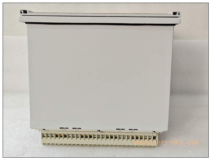
REM543CM216AAA
Application Scenarios & Product Features
Application Scenarios
‑ Medium‑large MV asynchronous / synchronous motor protection: pumps, mills, compressors in power‑plant, mining and heavy‑industry ‑ Small‑medium hydro‑/diesel‑/steam‑turbine generator main‑protection ‑ Marine and offshore platform rotating‑machine protection systems ‑ Legacy ABB REM543 system spare‑part replacement and bay‑retrofit projects
Core Features
‑ Full‑range rotating‑machine protection function‑library tailored for motors & generators ‑ Built‑in thermal‑overload model, motor‑stall detection and cumulative start‑up counter ‑ Stator differential protection (87G) for internal winding short‑circuit fault ‑ 15 binary‑inputs +12 relay‑outputs; expandable RTD temperature‑monitoring ‑ Embedded disturbance‑oscillography, event‑sequence logging, trip‑circuit supervision ‑ Multi‑protocol communication: SPA‑bus, Modbus‑RTU, IEC‑60870‑5‑103; IEC 61850 via external adapter ‑ IRIG‑B high‑precision time‑synchronization ‑ Built‑in programmable logic function for bay‑level interlocking logic ‑ Marine‑off‑shore certification for ship‑board and offshore‑platform deployment
Frequently Asked Questions (FAQ)
Q1: Device self‑supervision fault alarm after power‑on
A1: Check auxiliary‑supply voltage within rated range. Review self‑supervision fault‑code on local HMI. Confirm firmware‑version compatibility with hardware. Perform full power‑cycle reset. If alarm persists return unit for hardware inspection.
Q2: Protection element mis‑operation or refuse‑to‑operate under simulation test
A2: Check CT/VT wiring polarity and connection integrity. Verify setting‑group parameters match actual equipment rating. Confirm CT rated‑value (1 A /5 A) hardware jumper matches setting. Re‑calibrate analogue measuring channels via CAP501 tool.
Q3: Communication cannot connect with SCADA host
A3: Verify baud‑rate, station‑address and protocol‑mode setting. Check shield‑grounding of communication cable. Confirm wiring polarity of RS485 bus. Check bus‑terminator resistor installation. Review communication‑diagnostic counters in IED.
Q4: Can directly replace other variant?
A4: Physical dimension identical, but firmware‑option‑code, I/O‑configuration and setting‑file may differ. Need to cross‑check order‑code suffix; re‑download correct setting‑group before commissioning.
Q5: No disturbance‑record file after fault‑trip
A5: Confirm disturbance‑recording trigger‑conditions are enabled in setting‑group. Check storage‑resource status. Download records via CAP501 software; do not rely only on front‑panel operation.
Q6: What routine maintenance is required for protection IED?
A6: Every 6‑12 months inspect cabinet ventilation and dust accumulation; check terminal‑screw tightness. Regularly backup setting‑files. Periodically review self‑supervision alarm‑log and event‑history. Avoid long‑term over‑temperature cabinet‑environment. Do not clean circuit‑board by liquid solvent.

 Start Chat


 Send an Email


