
Description
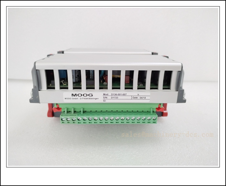
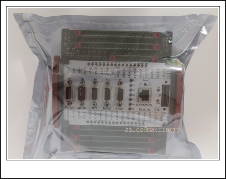
Moog D136-001-007 Two-Stage Electrohydraulic Servo Valve, D136 Series, Jet-Pipe Pilot Stage, High Precision Closed-Loop Hydraulic Control Valve
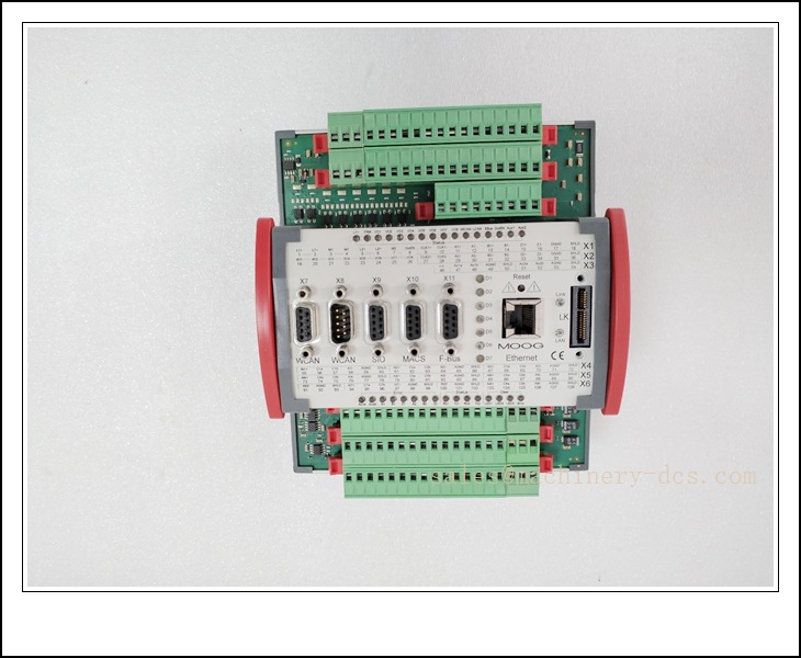
D136-001-007
Technical Specifications
- Catalog Number: D136-001-007
- Brand: Moog Inc.
- Product Type: 4-way two-stage electrohydraulic servo valve, jet-pipe first stage, spool second stage
- Rated Flow: 7 L/min @ 70 bar differential pressure
- Max Supply Pressure: 315 bar (4500 psi) intermittent; 210 bar (3000 psi) continuous
- Max Return Pressure: 35 bar (500 psi)
- Command Signal: ±10 VDC analog or ±20 mA current input
- Torque Motor: Dual coil configuration
- Frequency Response: Up to 80 Hz at -90° phase lag
- Hysteresis: <1.0% of rated flow
- Null Drift: Thermal null shift <0.5% rated flow
- Electrical Connector: MS3106A-10SL-4S 4-pin military circular connector
- Mounting Interface: Standard ISO 10372 manifold pattern
- Operating Fluid: Mineral hydraulic oil (ISO VG32 / VG46 / VG68)
- Required Fluid Cleanliness: NAS 8 or better, 3 μm absolute filtration
- Operating Temperature: -29 °C ~ +121 °C (-20 °F ~ +250 °F)
- Weight: ~2.5 kg
- Lifecycle Status: Legacy production model, available as spare / replacement
- Certifications: CE; suitable for industrial test and simulation platforms
Key Features & Advantages
- Jet-pipe pilot stage design: Superior contamination tolerance compared to traditional flapper-nozzle servo valves, lower sensitivity to fine particle debris.
- High dynamic response: Wide bandwidth supports fast closed-loop position, velocity and force control for test and simulation systems.
- Dual torque motor coils: Supports redundant drive schemes for safety-critical hydraulic axes.
- Low hysteresis and minimal thermal null drift: Delivers excellent repeatability and stable zero point during long test cycles and temperature swings.
- Compact standard manifold footprint: Direct interchangeability with other D136 series variants on existing test benches.
- 4-way hydraulic control: Bi-directional flow control for double-acting hydraulic actuators.
- Proven Moog D136 platform: Decades of field track record in structural test, motion simulation and industrial high-cycle presses.
- Compatible with standard Moog servo amplifiers: Simple integration into new or retrofitted hydraulic control systems.
Application Fields
- Aerospace structural fatigue test rigs and component test systems
- Flight motion simulators and hydraulic motion bases
- Material testing machines (tensile, compression, fatigue test)
- Metal forming presses, die cushion and blank holder force control
- Automotive durability test benches and suspension test systems
- Offshore and marine hydraulic precision control skids
- Steel mill roll gap and hydraulic gauge control
- Industrial force-controlled closed-loop hydraulic actuators
Related Product Recommendations
- D136-001-008: series higher flow variant
- -001-005: Lower flow jet pipe servo valve
- D631-004: Moog flapper-nozzle two-stage servo valve alternative
- D761: High-performance industrial servo valve family
- D936: Direct drive proportional servo valve with onboard electronics
- Moog G761: Classic general-purpose servo valve for lower dynamic requirements
- Moog servo amplifier: G122-822 / G122-823 analog drive card
- Hydraulic manifold ISO 10372 interface block
- 3 μm high-pressure servo-rated filter assembly
- D138 series: Upgraded jet pipe servo valve for new system design
Installation & Maintenance
Installation
- Mount the servo valve flat on a precision ground manifold; ensure manifold surface flatness ≤0.02 mm and surface finish Ra ≤0.8 μm.
- Use high-quality sealing gaskets; evenly torque mounting bolts to Moog specified torque sequence to avoid body distortion.
- Connect supply, return and actuator lines strictly following P, A, B, T port marking; separate servo lines from high-flow dump lines.
- Route the MS circular electrical connector away from hydraulic leak zones; secure cable strain relief and avoid pulling on pins.
- Match the command signal type (voltage or current) with your servo amplifier settings before pressurization.
- Flush the entire hydraulic circuit thoroughly before valve installation to remove weld slag and particulate contamination.
- Maintain the specified fluid cleanliness level; install dedicated pressure filter upstream of the servo valve.
- Avoid mounting locations with heavy continuous vibration and direct radiant heat sources.
Maintenance
- Monitor fluid particle count and oil condition on a scheduled basis; contamination is the leading cause of servo valve failure.
- Perform periodic null and hysteresis calibration using a hydraulic test stand after extended runtime or fluid contamination events.
- Inspect electrical connector pins for corrosion, oil ingress and loose locking rings during shutdown inspections.
- If performance degradation, drift or chatter appears, send the valve to an authorized Moog service center for bench rebuild, spool lapping and recalibration.
- Do not disassemble the valve body on-site; internal pilot and spool components require precision tooling and clean-room conditions.
- Keep spare -001-007 units for critical test rigs; save original calibration report and loop tuning parameters.
- After replacement, re-tune the closed-loop control loop and verify step response, bandwidth and null stability before returning to production testing.
- Document all oil sampling reports, valve calibration dates and overhaul history for asset traceability.

 Send an Email