
Description
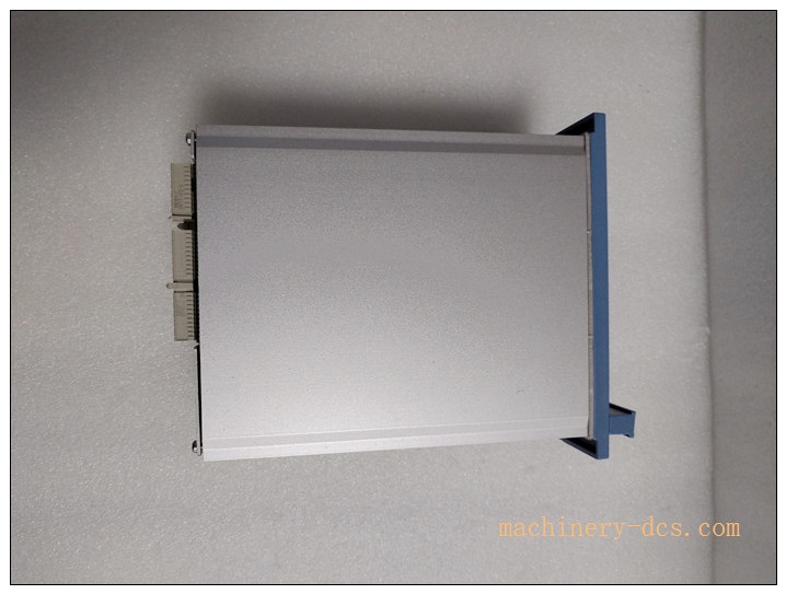
Honeywell FC‑QPP‑0001 Quad Processor Pack Module
Title
Honeywell FC‑QPP‑0001 Quad Processor Pack Safety CPU Module for Safety Manager / FSC SIS System
Meta‑Description
Honeywell FC‑QPP‑0001 is quad‑redundant safety processor pack (1oo4 architecture) for Honeywell Safety Manager SIS, executes safety application logic, supports hot‑standby redundant CPU operation, TÜV‑certified SIL3 IEC61508, installs in FS‑CPCHAS‑0001 controller chassis for petrochemical ESD and safety interlock systems.
FC-QPP-0001
Product Core Overview
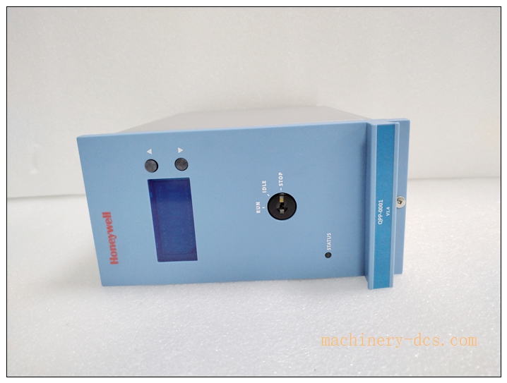
FC‑QPP‑0001 is the main safety processor module for Honeywell Safety Manager / FSC safety‑instrumented system. It adopts 1‑out‑of‑4 (1oo4) quad‑redundant internal processing architecture, four independent processor cores perform logic voting to achieve high‑reliability safety logic execution.
Multiple FC‑QPP‑0001 modules can be configured as dual redundant hot‑standby controller pair (A / B CPU). Active CPU runs safety logic; standby CPU synchronizes all logic data and can take over seamlessly upon active CPU failure. Module connects to chassis safety bus, communicates with I/O chassis (FC‑IOCHAS‑0001S / 0001R) to read field input signals and drive safety output modules. It works together with FC‑BKM‑001 battery‑key‑switch module for SRAM volatile‑data backup and hardware‑mode key‑lock control.
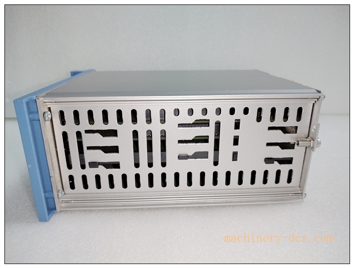
Front‑panel LED array indicates CPU status, run/program mode, fault diagnostic information. This module must be installed inside FS‑CPCHAS‑0001 controller chassis, cannot be mounted into I/O chassis. Widely deployed in oil‑gas and chemical SIL3 ESD interlock projects.
Note: This is legacy generation CPU; observe product lifecycle status. FC‑BKM‑001 is required accessory, sold separately.
Main Technical Specifications
| Item | Parameter |
|---|---|
| Part Number | FC‑QPP‑0001 |
| Module Type | Quad‑Redundant Safety Processor Pack (CPU) |
| Compatible System | Honeywell Safety Manager / FSC SIS |
| Internal Architecture | 1oo4 quad‑processor voting |
| Redundancy Mode | Dual‑CPU hot‑standby (A / B redundant pair supported) |
| Application Memory | SRAM (battery‑backed by FC‑BKM‑001), Flash non‑volatile memory |
| Communication | Internal safety‑bus to I/O chassis; engineering‑port for Safety‑Builder software |
| Safety Certification | TÜV SIL3, IEC 61508 / IEC 61511, CE, UL/cULus, FM |
| LED Indicators | RUN, PROGRAM, FAULT, CPU health status LED |
| Power Consumption | Max 12 W |
| Operating Temperature | 0 °C ~ +60 °C |
| Storage Temperature | −40 °C ~ +85 °C |
| Relative Humidity | 5‑95 % non‑condensing |
| Mounting | FS‑CPCHAS‑0001 controller chassis front‑plug‑in slot |
| Hot‑Swap | Mechanically hot‑pluggable; safety bypass procedure mandatory for live‑system replacement |
Quality Control Procedures
- Visual & Mechanical Incoming Inspection: Inspect PCB, front‑panel LED assembly, backplane gold‑plated connector, labeling; record serial‑number for full‑lifecycle traceability.
- Backplane Interface Continuity Test: Verify pin continuity, insulation and isolation for FS‑CPCHAS‑0001 backplane connector.
- Quad‑Core Voting Function Test: Validate 1oo4 internal processor voting mechanism under normal and simulated single‑core‑fault conditions.
- Redundant Hot‑Standby Test: Dual‑CPU pair synchronization and seamless switch‑over test between primary and standby processor.
- Memory‑Backup Interface Test: Verify SRAM backup interface cooperates with FC‑BKM‑001 battery‑module.
- Safety‑bus Communication Test: Validate reliable data exchange between FC‑QPP‑0001 and I/O chassis I/O modules.
- Environmental Stress Screening: Temperature‑cycle test covering full operating‑temperature range.
- EMC Compatibility Test: Industrial electromagnetic‑interference test.
- Final End‑of‑Line Validation & Archiving: Complete full‑function test suite; archive test‑records bound to unit serial‑number before factory release.
Related Brand Model Recommendations
- FS‑CPCHAS‑0001: Controller chassis for mounting FC‑QPP‑0001 and FC‑BKM‑001.
- FC‑BKM‑001: Battery & key‑switch module, mandatory matching accessory.
- FC‑IOCHAS‑0001S: Non‑redundant I/O chassis.
- FC‑IOCHAS‑0001R: Redundant I/O chassis variant.
- FC‑SDIL‑160824VDC: Loop‑monitored safety digital‑input module.
- FC‑SDO‑0824: Safety digital‑output module.
- FC‑SAI‑1620M: Safety analog‑input module.
- FC‑PSU‑UNI2450U: SIS 24VDC power‑supply unit.
Frequently Asked Questions (FAQ)
Q1: What is 1oo4 quad‑processor architecture? A: Four independent processor cores execute identical safety logic, perform cross‑voting. Mismatch triggers fault diagnosis, improves safety integrity to meet SIL3 requirements.
Q2: Can two FC‑QPP‑0001 run as redundant CPU pair? A: Yes. Install two FC‑QPP‑0001 inside FS‑CPCHAS‑0001 controller chassis for hot‑standby redundancy. Standby CPU keeps full synchronization; when main CPU fails, switch‑over happens automatically without process trip.
Q3: Is FC‑QPP‑001 usable inside I/O chassis FC‑IOCHAS‑0001S? A: No. Processor module must install in FS‑CPCHAS‑0001 controller chassis only.
Q4: Can I hot‑swap FC‑QPP‑0001 on running SIS rack? A: Mechanically hot‑plug possible. If single CPU configuration, system will trip during replacement. Under redundant dual‑CPU architecture, follow Honeywell maintenance procedure, confirm standby CPU takes over before removing faulty unit.
Q5: Can I repair module on‑site? A: No. Unauthorized disassembly voids SIL certification and warranty. Return defective unit to authorized service‑centre.
FC-QPP-0001
Installation & Configuration Guide
Pre‑Installation
- Inspect module for transit damage. Confirm part‑number FC‑QPP‑0001 and serial‑number match purchase‑order.
- Confirm FS‑CPCHAS‑0001 controller chassis, FC‑BKM‑001 battery‑key‑switch module, I/O chassis and I/O modules are complete.
- Prepare Safety Builder engineering software, configuration download cable, safety‑bus inter‑chassis cables.
- Review SIS project drawing: confirm single‑CPU or dual‑redundant CPU architecture definition.
Mechanical Installation
- Insert FC‑QPP‑0001 into target slot of FS‑CPCHAS‑0001 controller chassis from front panel, tighten quarter‑turn captive fasteners.
Important: For dual‑redundant configuration, install two FC‑QPP‑0001 modules in designated A / B slots. Do not force insertion; observe slot key‑position to avoid connector damage.
Electrical Wiring
- Complete chassis protective‑ground connection per SIS grounding specification.
- Connect safety‑bus cable between controller chassis FS‑CPCHAS‑0001 and I/O chassis FC‑IOCHAS‑0001S / 0001R.
- Connect 24VDC power supply from FC‑PSU‑UNI2450U to controller chassis power terminal.
- Connect engineering download cable for Safety‑Builder software access.
System Configuration & Commissioning
- After finishing hardware installation, power‑on SIS system. Observe FC‑QPP‑0001 front‑panel LED status.
- Launch Honeywell Safety‑Builder software, connect to processor, confirm FC‑QPP‑0001 and FC‑BKM‑001 are correctly recognized.
- Complete hardware configuration in project, download full safety‑logic application to CPU flash memory.
- For dual‑redundant CPU: verify data synchronization between primary and standby CPU, test automatic switch‑over function by simulating main CPU fault.
- Cooperate with I/O chassis to test input / output channels and all diagnostic‑alarm functions.
- Test key‑switch function via FC‑BKM‑001 (RUN / PROGRAM / FORCE mode).
- Save full‑project‑configuration‑backup‑file, system enters formal SIL3 safety‑interlock operation.

 Start Chat


 Send an Email


