
Description
GE Reuter‑Stokes RS‑E2‑0285 Flame Sensor Interconnect Cable Assembly (Gas Turbine UV Flame Detector Cable)
Product Detailed Information
RS‑E2‑0285 is a high‑temperature rated flame‑sensor interconnection cable assembly manufactured by Reuter‑Stokes (GE Vernova). It serves as dedicated signal transmission cable for RS‑FS‑9004 series UV flame sensors deployed on industrial gas turbines. This assembly delivers UV detector low‑level signal from field‑mounted flame sensor head to turbine flame‑amplifier / protection rack. Full‑part variants include suffix extensions such as RS‑E2‑0285P004, RS‑E2‑0285P012, RS‑E2‑0285P013, where trailing suffix defines exact cable length and connector configuration. Cable is built with high‑temperature insulation, shielded multi‑conductor construction, fitted with MIL‑DTL‑38999 Series‑III military‑spec circular metal connectors at both ends for harsh turbine‑enclosure environment. OEM production is discontinued; new‑old‑stock, tested refurbished and field‑recovered spare cable assemblies are widely used for gas‑turbine protection‑system life‑extension maintenance projects.
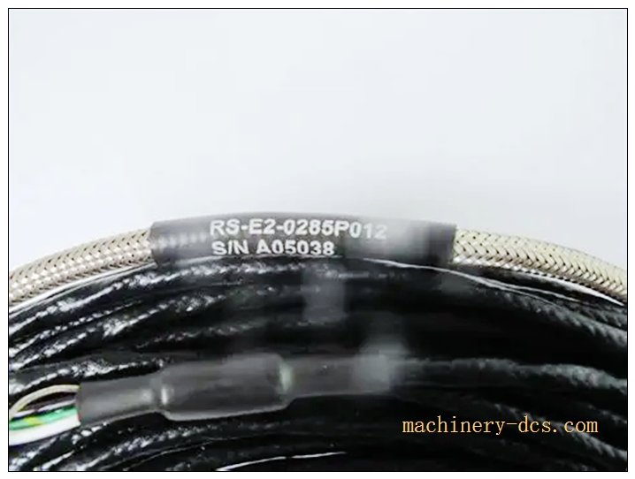
RS‑E2‑0285
Technical Parameters
| Item | Specification |
|---|---|
| Manufacturer | GE Reuter‑Stokes (GE Vernova) |
| Model | RS‑E2‑0285 (suffix P‑codes define length & connector option) |
| Product Status | OEM Discontinued, spare‑part‑only supply |
| Application | UV flame‑sensor signal cable for RS‑FS‑9004 flame detector |
| Connector Type | MIL‑DTL‑38999 Series III circular metal shell connectors, bayonet coupling |
| Cable Construction | Multi‑pair overall shielded high‑temperature instrumentation cable |
| Maximum operating temperature | 250 °C (482 °F) continuous rating for turbine enclosure routing |
| Insulation material | High‑performance heat‑resistant fluoropolymer insulation |
| Shielding | 100% coverage overall shield for EMI/RFI suppression against turbine‑site high‑frequency noise |
| Available standard lengths | P004‑4ft; P012‑120ft; P013‑custom length variant |
| Signal type | Low‑level UV pulse signal (no power‑carrying high‑voltage circuit) |
| Mounting | Routed inside gas‑turbine enclosure, cable‑gland / tray installation |
| Storage Temperature | ‑40 ℃ ~ +125 ℃ |
| Humidity | 5‑95 % RH non‑condensing |
| Certifications | GE gas‑turbine qualified, meets industrial turbine fire‑safety requirements |
Compatibility & Installation Traps
Compatibility
- Reuter‑Stokes RS‑FS‑9004 UV flame sensor detector head (mandatory mating field device)
- GE gas‑turbine flame amplifier / flame‑monitor protection modules for GE heavy‑duty gas turbines
- MIL‑DTL‑38999 series‑III mating receptacles on flame‑amplifier cabinet side
Critical note: RS‑E2‑0285 is low‑level UV‑signal‑only cable. It cannot be substituted for general‑purpose thermocouple cable or regular instrument cable. Always verify complete full part‑number including P‑suffix code; different suffix represents different physical length and connector pin‑out, cannot direct swap.
Installation Pitfalls
- High‑temperature routing constraint: Cable must run within rated 250 °C ambient. Do not route directly touching hot turbine casing surfaces; maintain thermal stand‑off distance or use heat‑shield conduit. Exceeding temperature rating degrades fluoropolymer insulation and causes intermittent signal leakage / short‑circuit.
- Connector handling risk: MIL‑38999 bayonet connectors shall not be forced‑mated. Keep connector shells clean, free of turbine‑oil dust and carbon deposits. Damaged pin contacts produce sporadic flame‑signal dropout and false flame‑out trips.
- Separation from high‑power cables: Must physically separate from high‑voltage ignition cables, motor power cables. Low‑amplitude UV signal is extremely susceptible to EMI interference; parallel‑routing creates spurious flame‑detection triggering.
- Shield termination requirement: Cable shield must follow GE‑specified single‑end grounding scheme. Double‑ended grounding introduces ground‑loop noise, leading to unstable flame‑strength readings.
- Minimum bend radius violation: Observe cable minimum bend‑radius requirement; sharp tight bends crack high‑temperature fluoropolymer insulation over thermal cycling.
- Mechanical abrasion risk inside turbine enclosure: Protect cable against vibration‑induced friction against metal structures; add cable‑glands and anti‑chafing sleeving. Vibration‑rubbing will breach shielding and insulation.
- Part‑number suffix validation: Confirm full marking RS‑E2‑0285 + P‑suffix. Using wrong‑length variant will make field installation impossible; generic non‑Reuter‑Stokes cable cannot replicate original low‑level UV‑signal performance.
- Post‑replacement loop‑test mandatory: After cable swap, perform flame‑sensor loop‑test with turbine‑protection test tool; verify flame‑strength signal magnitude, check for false‑flame / no‑flame fault alarms before returning unit to service.
Standard Operating Procedure (SOP)
- Pre‑work: Execute plant lock‑out‑tag‑out for gas‑turbine unit. Confirm turbine is fully shut‑down, cooldown completed, isolation of ignition and protection circuits. Wear certified ESD anti‑static wrist strap.
- Data backup: Record full cable part‑number including P‑suffix, document connector pin assignment, existing flame‑strength signal baseline value from turbine HMI / DCS; export flame‑monitor fault history log.
- Cable removal: De‑energize flame‑monitor amplifier rack. Unlock and disconnect MIL‑38999 circular connectors both at flame‑sensor head and cabinet amplifier side. Release cable tray fasteners, pull out old RS‑E2‑0285 cable assembly. Inspect connector pins for corrosion, oil contamination, bent pins; inspect tray‑route for chafing marks.
- Incoming inspection: Visual inspect spare RS‑E2‑0285 cable assembly; verify full part‑number including P‑suffix code. Inspect both‑end MIL‑38999 connector shells, pin contacts, insulation jacket for scratches, cracks or contamination.
- Mechanical mounting: Route new cable assembly through turbine cable‑tray path identical to original routing. Install anti‑chafing protection where cable contacts metal structures; maintain minimum bend radius and thermal stand‑off from hot casing components. Secure cable‑tray fasteners.
- Cabling: Carefully mate both‑end MIL‑DTL‑38999 bayonet connectors until positive lock‑click. Perform shield‑ground termination strictly following GE single‑end grounding instruction. Avoid over‑torquing connector shells.
- Power‑on commissioning: Restore flame‑monitor amplifier control power. Clear historical fault logs inside turbine protection system.
- Functional validation: Execute flame‑sensor loop functional test. Verify real‑time flame‑strength signal reading matches expected baseline. Simulate flame‑present / flame‑loss condition to validate protection‑logic response. Confirm no persistent cable‑fault or flame‑signal‑dropout alarms. Cross‑check value on local turbine HMI and DCS system.
- Documentation: Fill gas‑turbine maintenance log; archive cable assembly serial / part‑suffix information, loop‑test‑result records. Properly package defective removed cable assembly. Release lock‑out‑tag‑out permit only after full acceptance‑test successfully completed.
Application Scenarios
‑ Heavy‑duty industrial gas‑turbine UV flame‑detection protection system signal wiring ‑ Transfer low‑level UV detector signal from RS‑FS‑9004 flame‑sensor head to flame‑amplifier cabinet ‑ Prevent false flame‑trip / false flame‑present alarms for gas‑turbine safety‑protection logic ‑ Legacy Reuter‑Stokes flame‑detection platform preventive maintenance & life‑extension retrofit projects
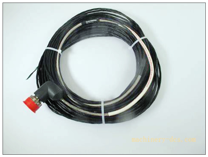
RS‑E2‑0285
Matching & Supporting Components
- RS‑FS‑9004 UV flame sensor detector head (matching field sensor)
- GE gas‑turbine flame amplifier / flame‑monitor protection modules
- MIL‑DTL‑38999 series‑III connector cleaning tool and contact inspection kit
- Anti‑chafing high‑temperature sleeving for turbine‑enclosure cable‑protection
- ESD‑shielded anti‑static storage bag for spare cable‑assembly storage
Brand‑Related Alternative & Recommended Models
- RS‑E2‑0285P004 / RS‑E2‑0285P012 / RS‑E2‑0285P013: Different‑length variants of same cable family, select correct P‑suffix for site‑required length
- RS‑FS‑9004: UV flame‑sensor head itself; separate device from cable assembly
- Modern GE‑Vernova integrated flame‑detection system: For complete system‑migration new‑build projects

 Start Chat


 Send an Email


