
Description
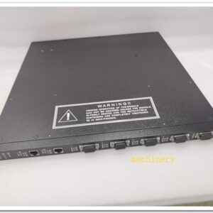
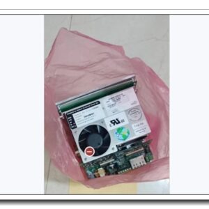
The GE Fanuc IC697BEM731 is a Bus Expansion Master Module
Product Title & Description
Model: IC697BEM731 The GE Fanuc IC697BEM731 is a Bus Expansion Master Module designed for the GE Series 90-70 PLC platform. It serves as the master interface for extending remote I/O racks across multiple chassis, enabling high-speed backplane bus communication between the main CPU rack and expansion racks. Widely deployed in power generation, water treatment, metallurgy and heavy manufacturing automation systems, this module delivers reliable distributed I/O expansion for large-scale industrial control applications.
Core Product Overview
The IC697BEM731 is a key bus master unit within the GE Series 90-70 PLC family. Installed in the main CPU rack, it controls the Genius bus or expansion bus to communicate with remote slave racks. It manages data exchange, rack status monitoring and fault reporting between the primary chassis and remote expansion I/O racks. This module simplifies system expansion without overloading the main processor. It supports multiple remote racks, provides built-in diagnostic functions for bus communication errors, rack loss and wiring faults. It is hot-swappable under proper system configuration, reducing downtime during maintenance and replacement. It is commonly used to distribute I/O hardware over longer distances for large process control systems.
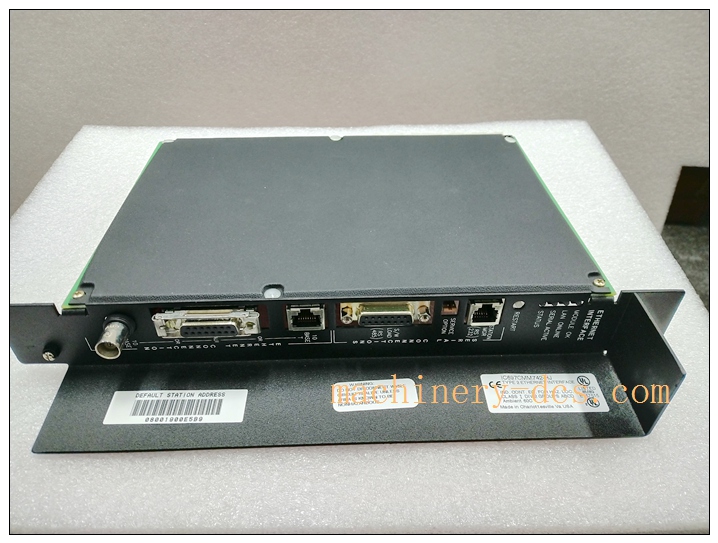
IC697BEM731
Main Technical Specifications
- Manufacturer: GE Fanuc (GE Automation)
- Part Number: IC697BEM731
- Product Type: Bus Expansion Master Module
- Series: Series 90-70 PLC
- Function: Master control for remote expansion racks
- Bus Type: Genius I/O Bus / Series 90-70 Expansion Bus
- Number of supported remote racks: Up to 8 expansion racks
- Backplane Current Draw: 5 VDC, typical 1.2 A
- Communication rate: Genius bus standard speed
- Diagnostic features: Bus fault detection, rack missing alarm, module status LED indicators
- Mounting: Single slot in Series 90-70 PLC chassis
- Operating Temperature: 0°C ~ +60°C
- Ambient Humidity: 5% to 95%, non-condensing
- Isolation: Bus isolation between main backplane and remote bus circuit
- Certifications: CE, UL, CSA for industrial control use
Quality Control Procedures
GE Fanuc modules are manufactured under ISO9001 quality management system and comply with IEC industrial control standards.
- Incoming Material Inspection: All PCBs, integrated circuits and passive components are sourced from approved suppliers and undergo 100% incoming quality inspection.
- Automated Assembly & Serial Traceability: SMT assembly and soldering are automated. Each unit has a unique serial number for full production traceability.
- Full Functional Testing: Every finished module undergoes bus communication test, LED status verification, rack recognition test and fault simulation test.
- Environmental Stress Screening: Batch samples are subjected to temperature cycling, vibration and EMC testing to validate stability in harsh industrial sites.
- Final Inspection & Packing: Units passing all tests are visually inspected, labeled, packed with anti-static and shock-resistant packaging and shipped with factory test records.
Brand Related Model Recommendations
- IC697BEM711: Basic bus expansion master for simpler rack expansion requirements.
- IC697BEM733: Enhanced bus master variant with improved noise immunity for high EMI environments.
- IC697BEM732: Older generation bus master, predecessor of IC697BEM731.
- IC697BEM741: High-speed bus master for larger distributed I/O systems. All models fit Series 90-70 chassis, share the same programming software environment for easy migration and spare part replacement.
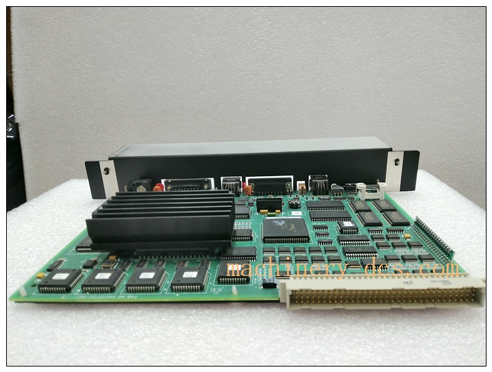
IC697BEM731
Frequently Asked Questions (FAQ)
Q1: Which PLC system does belong to? A1: It belongs to GE Series 90-70 PLC system, working with Series 90-70 CPU and corresponding expansion racks.
Q2: What is the main purpose of ? A2: It acts as bus master in the main rack to communicate and control multiple remote expansion I/O racks, extending the PLC I/O capacity.
Q3: Is this module hot swappable? A3: Yes, hot-swap is supported when the Series 90-70 system is configured appropriately. Follow GE official operation procedures during replacement.
Q4: How many remote racks can drive? A4: It supports up to 8 remote expansion racks on the bus.
Q5: What is the warranty for original GE Fanuc ? A5: Original unit comes with standard 12-month factory warranty against manufacturing defects under correct installation and operating conditions.
Installation & Configuration Guide
7.1 Pre-installation Preparation
Confirm part number and inspect module for physical damage. Prepare Series 90-70 chassis, bus cables, terminal connectors and programming software. Power off the PLC chassis before handling. Wear ESD protection to avoid electrostatic damage to circuit boards. Check bus cable length and grounding plan according to GE wiring specifications.
7.2 Installation Steps
Insert into an available slot in the main CPU rack and lock the module retaining latch. Wire the expansion bus cable between this master module and each remote slave rack. Secure cable connections and properly ground cable shields. Check all bus wiring to eliminate short circuit or reversed connection risks. Reserve adequate airflow space around the chassis for heat dissipation.
7.3 System Configuration & Commissioning
Launch GE programming software, add into hardware configuration. Define the quantity and types of remote expansion racks in the project. Download hardware configuration to Series 90-70 CPU. Power up racks sequentially. Verify module LED status, bus connection and rack recognition. Simulate communication faults to test diagnostic alarms. Record commissioning parameters and bus status logs.
7.4 Maintenance & Precautions
Regularly inspect cable tightness, connector condition and module temperature during planned outages. Keep cabinet clean and avoid excessive dust or corrosive gas. Do not exceed the maximum number of remote racks supported. Do not open the module housing. If bus communication failure occurs, first inspect bus cables, grounding and remote rack power supply before replacing the module.

 Start Chat


 Send an Email


