
Description
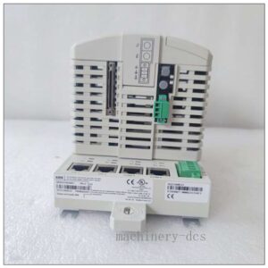
8502‑BI‑DP Bus Interface Module (BIM) for MTL8000 I/O SystemEaton
Brand: EATON (Formerly MTL Instruments)
Model: 8502‑BI‑DP
Product Series: MTL8000 Intrinsically‑Safe Remote I/O System
Country of Origin: United Kingdom
Product Type: PROFIBUS‑DP Slave Bus Interface Module (BIM)
Status: Obsolete / Discontinued production, spare‑part & refurbished supply onlyEaton
Product Core Overview
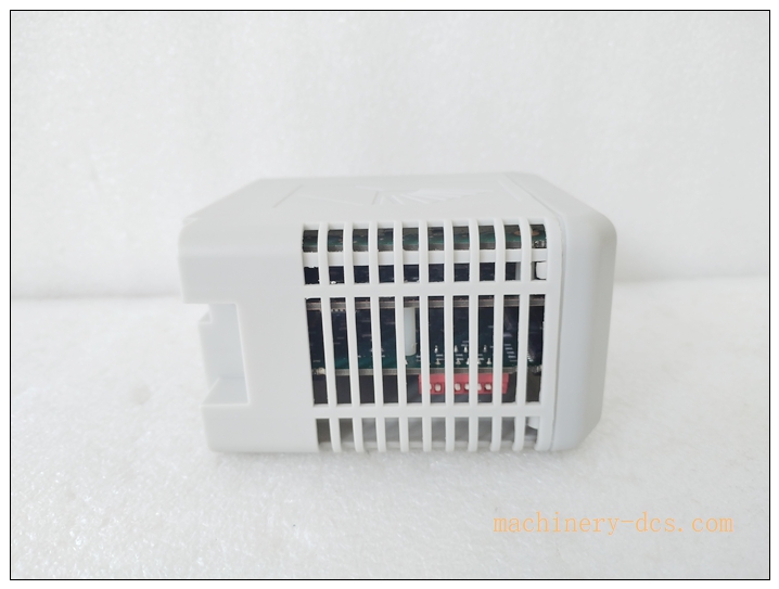
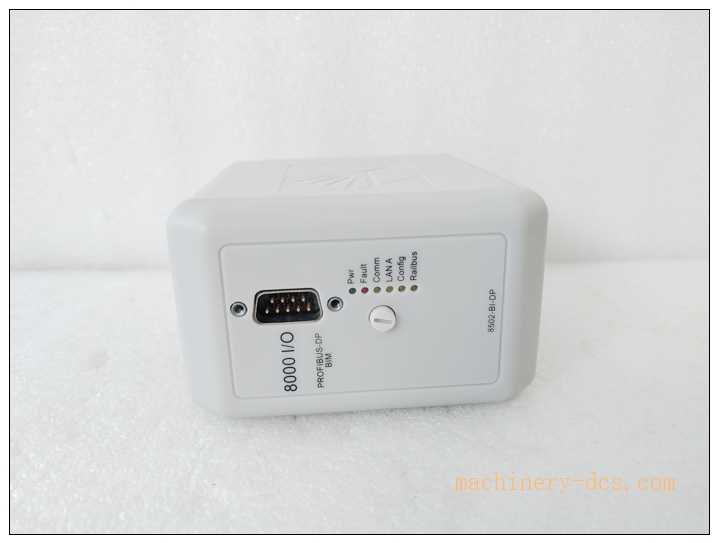
The 8502‑BI‑DP is a bus‑interface module (BIM) for the MTL8000 intrinsically‑safe remote I/O rack system. It acts as PROFIBUS‑DP slave, bridging the MTL8000 Railbus backplane and PROFIBUS‑DP master host (Siemens PLC / DCS)Eaton.
It collects data from up to 24 local MTL8000 I/O modules, handles cyclic I/O exchange, extended channel‑level diagnostics, and transparent HART tunnelling over PROFIBUS‑DP. Configuration is stored in onboard non‑volatile memory. Suitable for hazardous‑area process automation in oil‑gas, chemical and petrochemical plants; widely used for existing MTL8000 rack spare‑part replacement & retrofits.
8502‑BI‑DP
Main Technical Specifications
| Parameter | Specification |
|---|---|
| Manufacturer | EATON MTL Instruments |
| Model | 8502‑BI‑DP |
| Function | PROFIBUS‑DP Slave Bus‑Interface Module (BIM) for Railbus |
| PROFIBUS Interface | 9‑pin D‑Sub female, RS‑485, complies with EN50170 |
| Galvanic Isolation | 500 V AC between PROFIBUS‑DP and Railbus backplane |
| Supported Baud Rates | 9.6 k‑ 12 M baud auto‑sensing |
| Max I/O Modules per BIM | 24 pieces I/O modulesEaton |
| Max Cyclic Data | 244 bytes input; 244 bytes output; max 78 bytes diagnostic telegramInnoPLC Sy… |
| Protocol Features | PROFIBUS‑DP‑V0 cyclic exchange; extended diagnostics; HART tunnelling over DP |
| Configuration Methods | MTL 8455‑SW‑CF software; PROFIBUS configurator; download from 8510‑NS‑MO node‑service moduleEaton |
| Power Supply | Powered by Railbus 12 V; typical 420 mA; max 520 mA @‑40 °CInnoPLC Sy… |
| LED Indicators | Power/Fail, LAN Activity, Railbus status |
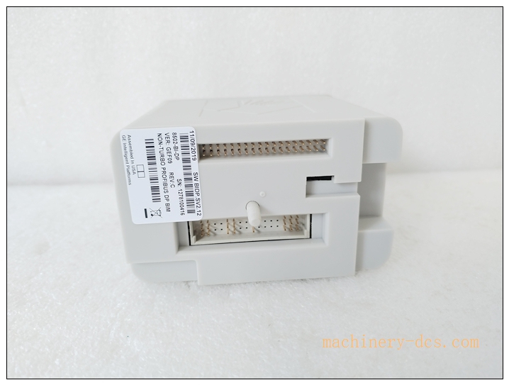
| Mounting | Slot‑mount inside rack backplane |
| Dimension | 63 mm width |
| Weight | Approx 350 gInnoPLC Sy… |
| Operating Temperature | −40 °C ~ +70 °C |
| Storage Temperature | −40 °C ~ +85 °C |
| Certifications | CE, ATEX, UL for hazardous‑area system integration |
| Warranty | 12‑month |
related models
- 8502‑BI‑DP: PROFIBUS‑DP Bus‑Interface Module (reference model)
- 8502‑BI‑DN: DeviceNet BIM module for
- 8502‑BI‑MB: Modbus‑RTU BIM module for
- 8510‑NS‑MO: Node Services Module for local configuration & auto‑setup
- 8501‑PS‑DC: rack power‑supply unit
- 8455‑SW‑CF: MTL configuration software for BIM parameterisation
8502‑BI‑DP
Professional Quality Control & Test Standard Operating Procedure (SOP)
- Incoming Component Inspection Inspect main processor, PROFIBUS RS485 transceiver, isolation circuit, non‑volatile memory and backplane Railbus connector. Verify components comply with EATON‑MTL hazardous‑area grade specifications; reject non‑conforming components.
- PCB Assembly & Bench Functional Test After assembly, perform power‑on self‑test. Verify Railbus handshake, PROFIBUS‑DP physical‑layer signal quality. Simulate PROFIBUS‑DP master communication; validate cyclic I/O data exchange, extended diagnostic telegram and HART tunnelling function. Test configuration store‑and‑restore in non‑volatile memory.
- Thermal Burn‑in Aging Test 72‑hour powered burn‑in test at 55 °C ambient. Run cyclic PROFIBUS‑DP traffic, continuous Railbus I/O data polling. Monitor communication stability and memory integrity to screen early‑life hardware defects.
- Environmental Compliance Validation Temperature cycling, vibration‑shock and EMC EMI/EMS testing comply with IEC 61000‑series and ATEX related standards, simulating petrochemical plant hazardous‑area cabinet environment.
- Full‑system rack integration test Insert 8502‑BI‑DP into rack, populate mixed analogue/digital I/O modules. Download configuration via 8455‑SW‑CF; import GSD file to PROFIBUS master. Verify cyclic data, channel‑level fault diagnostics, HART variable transmission and LED status feedback.
- Final calibration & batch‑sampling release Firmware version validation; 5 % random‑sample retest per batch. Record serial‑number and firmware revision. Generate traceable factory‑test reports before labelling and shipment.
Installation Guidelines
Safety note: system is for intrinsically‑safe field‑signal application. Observe ATEX installation rules; do not hot‑swap modules in hazardous zone unless cabinet meets Zone 2 requirements.
6.1 Pre‑installation Preparation
Power‑off rack Railbus power. Wear anti‑static wristband for ESD protection. Verify full model 8502‑BI‑DP and firmware revision match original spare‑part. Inspect for mechanical damage, bent backplane pins. Prepare PROFIBUS‑DP shielded cable, bus terminator, GSD file and 8455‑SW‑CF configuration software.
6.2 Hardware Rack Installation
Slide 8502‑BI‑DP into dedicated BIM slot within rack chassis, ensure Railbus backplane connector fully seated. Connect PROFIBUS‑DP cable to D‑Sub 9‑pin port; install external bus terminator at physical bus segment end‑point. Route PROFIBUS signal cable separate from high‑power cables; apply proper shield grounding according to PROFIBUS installation guideline.
6.3 System Configuration & Commissioning
Power‑up rack. Install corresponding GSD file in PROFIBUS‑DP master engineering tool. Configure PROFIBUS station address, baud‑rate, I/O mapping and diagnostic options. Download BIM configuration via 8455‑SW‑CF software or via PROFIBUS host. Bring PROFIBUS‑DP network online; confirm BIM enters data‑exchange state, verify each I/O channel data and diagnostic status. Save complete configuration file for offline backup.
6.4 Post‑installation Validation
Check front‑panel LED status indicators. Verify cyclic I/O data consistency between PROFIBUS master and field channels. Trigger channel fault simulation to validate extended diagnostic reporting. Run continuous 4‑hour runtime test. Confirm no communication drop‑outs, no false fault alarms, complete commissioning acceptance.
Application Scenarios & Product Features
Application Scenarios
‑ Petrochemical, refinery, offshore‑platform intrinsically‑safe remote I/O system ‑ Chemical plant hazardous‑area measurement & control based on rack ‑ Oil‑gas process DCS‑PLC integration via PROFIBUS‑DP ‑ Legacy I/O rack spare‑part replacement and system retrofit projects
Core Features
‑ PROFIBUS‑DP‑V0 slave interface for intrinsically‑safe remote‑I/O rack ‑ Support up to 24 pieces I/O modules per BIM node ‑ Transparent HART variable tunnelling over PROFIBUS‑DP ‑ Rich extended channel‑level diagnostic information for fault localisation ‑ Non‑volatile onboard memory stores complete node configuration ‑ Multiple configuration paths: local software, PROFIBUS host or node‑service module ‑ 500 V isolation between PROFIBUS‑DP field‑side and internal Railbus backplane ‑ ATEX‑compliant for hazardous‑area system integration
Frequently Asked Questions (FAQ)
Q1: Module LAN LED no activity after rack power‑on
A1: Check Railbus power supply. Confirm module fully seated in BIM slot. Verify PROFIBUS baud‑rate match between master and BIM; check bus‑terminator installation and D‑Sub connector contact. Perform full rack power‑cycle. If fault persists return unit for hardware inspection.
Q2: PROFIBUS‑DP cannot enter data‑exchange state
A2: Confirm correct GSD file version loaded in PROFIBUS master. Verify station‑address and baud‑rate consistency. Check PROFIBUS cable shielding, termination and D‑Sub pin integrity. Review BIM diagnostic counters for bus error messages.
Q3: Individual I/O channel data missing / invalid
A3: Check I/O module physical seating in rack. Verify node configuration includes corresponding channel mapping. Read extended diagnostic telegram to locate faulty slot/channel.
Q4: HART variables cannot be read over PROFIBUS‑DP
A4: Confirm field I/O module supports HART function. Enable HART tunnelling parameter inside BIM configuration. Verify PROFIBUS master cyclic data mapping includes HART variable bytes.
Q5: Can 8502‑BI‑DP be hot‑swapped?
A5: Hot‑swap is allowed only for cabinet located in Zone 2 / safe area. Not permitted inside Zone 0 / Zone 1 hazardous‑area without proper cabinet certification.
Q6: What routine maintenance is required for 8502‑BI‑DP?
A6: Every 6‑12 months inspect cabinet ventilation and dust accumulation; check rack backplane contact and PROFIBUS D‑Sub connector tightness. Backup complete node configuration file. Avoid long‑term cabinet over‑temperature operation. Do not clean circuit‑boards with liquid solvent. Periodically monitor PROFIBUS diagnostic error counters.

 Start Chat


 Send an Email


