
Description
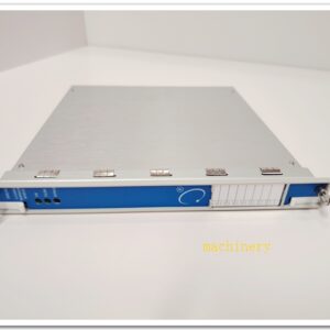
Eaton MTL831C Intrinsically Safe Analog Temperature Multiplexer Transmitter, MTL830C System, 16-Channel Mixed TC / RTD / mV / Potentiometer Input
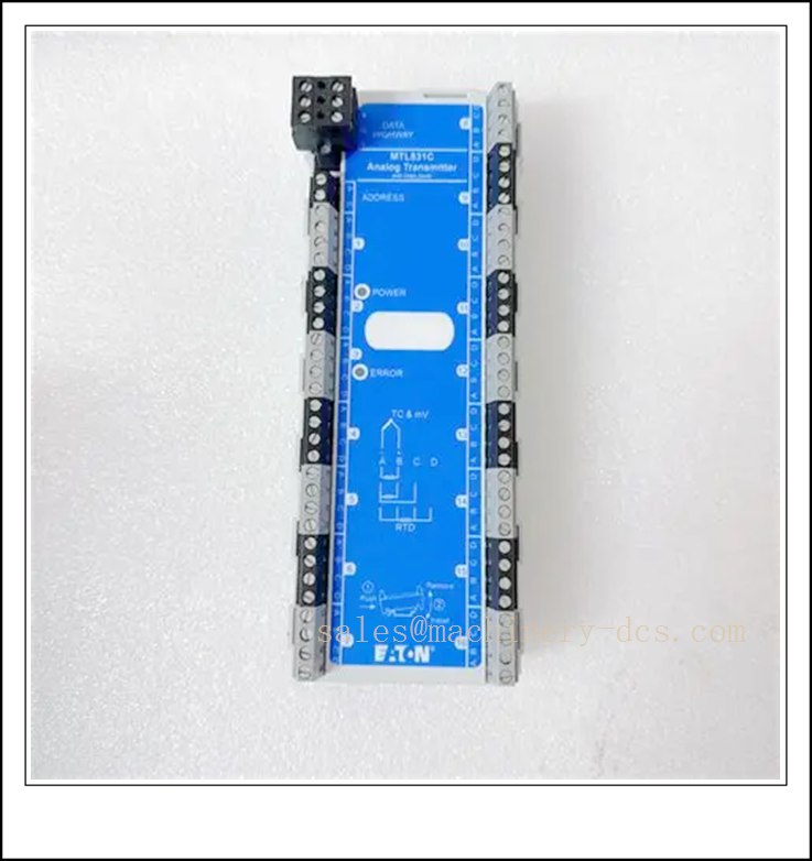
MTL831C
Technical Specifications
- Catalog Number: MTL831C (MTL831C‑PS = pluggable terminal version)
- Brand: Eaton MTL
- Product Type: Hazardous‑area analog multiplexer transmitter, part of MTL830C temperature multiplexer system
- Channel Count: 16 universal input channels, software configurable per channel
- Supported Input Types: Thermocouple (B, C, E, J, K, N, R, S, T, XK), 2/3/4‑wire RTD, ±100 mV, potentiometer up to 550 Ω
- RTD Range (Pt100): -200 °C ~ +850 °C
- Accuracy (21 °C):
- mV: ±0.045% of reading or ±20 µV (whichever greater)
- TC: ±0.04% of reading or ±18 µV (whichever greater)
- Response Time: Typical 500 ms per scan cycle
- Power: Loop powered via data highway; no separate local power supply in hazardous zone
- Data Highway: Single shielded twisted pair, carries power + bidirectional communication
- Max length: 1 km (IS installation with MTL5553), up to 2 km (non‑IS)
- Capacity: 1 or 2 × MTL831C can connect to one MTL838C receiver
- Safety Certification: ATEX, IECEx, FM / FMc; Ex ia IIC T4 Ga, suitable for Zone 0
- Operating Temperature: -40 °C ~ +70 °C; storage -40 °C ~ +85 °C
- Weight: 0.26 kg
- Indicators: Green power LED, red fault LED
- Mounting: Install inside certified hazardous‑area junction enclosure
- Compliance: IEC 60079 intrinsic safety standards
Key Features & Advantages
- 16 mixed universal sensor inputs: Same unit accepts thermocouples, RTDs, mV and potentiometer signals; software configuration without hardware jumpers.
- Zone 0 intrinsically safe design: Can be mounted directly in the hazardous area close to temperature sensors, drastically reducing expensive field IS wiring.
- Single-pair data highway: Consolidates all 16 sensor measurements onto one shielded twisted cable back to safe area, cutting field wiring cost up to 50%.
- Sensor fault detection: Open-circuit, short-circuit and sensor break diagnostics reported over Modbus to host DCS/PLC.
- No local hazardous-area power: Powered remotely from the safe‑side receiver through the highway, simplifying field cabinet design.
- Interoperable receiver options: Pair with MTL838C (Modbus RTU / RS‑485) or MTL838C‑MBT (Modbus TCP Ethernet).
- Two-unit daisy‑chain support: One receiver can serve up to 32 sensor points using two MTL831C transmitters.
- Two terminal variants available: Fixed screw terminals (MTL831C) or pluggable terminals (‑PS) for faster replacement.
Application Fields
- Oil & gas wellheads, offshore platforms and pipeline temperature monitoring
- Refinery and petrochemical furnace, reactor and column temperature points
- Chemical batch and continuous process hazardous temperature loops
- LNG storage, compression and cryogenic temperature measurement
- Power plant hazardous auxiliary skids and burner thermocouple arrays
- Pharmaceutical classified hazardous process areas
- Multi-point temperature skids requiring intrinsic safety consolidation
- Fire and gas systems with distributed temperature sensors
Related Product Recommendations
- MTL831C‑PS: MTL831C with pluggable terminals
- MTL838C: Safe‑area Modbus RTU receiver (RS‑485)
- MTL838C‑MBT: Safe‑area Modbus TCP Ethernet receiver
- MTL5553: FF H1 isolator / power supply, mandatory for Zone 0 IS highway
- FCS‑9616 / FCS‑9632: MTL certified hazardous field junction boxes
- MTL5541: 4–20 mA IS analog input isolator (single-loop alternative)
- MTL5544: 4–20 mA IS analog output isolator
- MTL5575: HART isolator for conventional transmitters
- MTL831B: Legacy predecessor model (for spare reference only)
- MTL7787+: Shunt-diode fieldbus barrier for alternative IS topologies
Installation & Maintenance
Installation
- House inside a certified Ex ia enclosure in the hazardous zone; mount vertically and maintain adequate clearance.
- Route individual sensor cables to each channel; wire RTDs strictly following 2/3/4‑wire terminal assignments for best accuracy.
- Use shielded twisted‑pair cable for the data highway. For Zone 0 IS layout, insert MTL5553 isolator between MTL838C receiver and the highway.
- Maintain polarity (+ / -) on the data highway; shield bonding must follow site IS earthing drawings to avoid ground loops.
- Configure each input channel type via the receiver software after all field sensors are wired.
- Verify all connected sensors hold compatible IECEx / ATEX entity parameters before energising the highway.
- Separate low-level thermocouple/RTD wiring from high‑voltage AC and VFD cables to minimise thermal and electrical noise.
Maintenance
- Perform routine inspection at least every 2 years; shorten interval for coastal, corrosive or high‑humidity environments, complying with IEC 60079‑17.
- Check green power LED is blinking and red fault LED remains off; inspect terminals, cable insulation and enclosure integrity.
- Use Modbus host diagnostics to identify broken sensors, open loops or highway communication faults.
- Do not open or modify internal circuitry in hazardous classified areas.
- If replacement is required, swap with the matching or ‑PS spare; re‑validate channel configuration after replacement.
- Keep intrinsic safety labels intact and retain system topology, sensor list and entity parameter documentation for hazardous area audit.
- Clean enclosure exterior only with a lightly dampened cloth; avoid harsh solvents.

 Send an Email