
Description
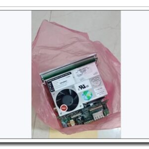
Eaton MTL5553 Intrinsically Safe Fieldbus Isolator / Power Supply, 31.25 kbit/s H1 Foundation Fieldbus Extender, MTL5500 Series
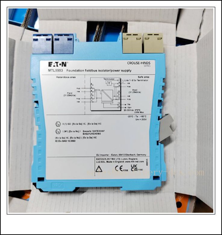
MTL5553
Technical Specifications
- Catalog Number: MTL5553
- Brand: Eaton MTL
- Product Type: Intrinsically safe fieldbus isolator & power supply, H1 FF bus extender
- Bus Rate: 31.25 kbit/s, Foundation Fieldbus H1, compliant with IEC 61158-2
- Input Supply Voltage: 20–35 VDC
- Max Hazardous Side Output Current: 80 mA
- Hazardous-side Output: 18.4 V nominal, DC impedance 105 Ω
- Safety Parameters (Hazardous Area): 22 V, 102 Ω, 216 mA; Um = 250 V rms / DC
- Galvanic Isolation: 250 V AC isolation between safe area, hazardous area and supply circuits
- Power Dissipation: 2.3 W typical @24 VDC, 2.6 W maximum @35 VDC
- Indicator: Green LED for power status
- Mounting: DIN rail, 16 mm slim module width
- Operating Temperature: -20 °C ~ +60 °C (-4 °F ~ +140 °F)
- Humidity: 5%–95% RH, non‑condensing
- Approvals: ATEX, IECEx, FM / FMc; suitable for Zone 0, IIC, T4–T6 hazardous locations
- Termination: Removable pluggable terminal connectors; internal bus terminator configurable via jumper
- Compliance: Foundation Fieldbus Type 133 IS power supply profile
Key Features & Advantages
- H1 Fieldbus extension into Zone 0: Purpose-built to carry both power and FF H1 communication to fieldbus instruments in hazardous areas.
- 3-port galvanic isolation: Separates safe-side bus, hazardous-side field network and supply, eliminates ground loop issues; no mandatory IS earth required.
- Integrated configurable bus terminator: Internal terminator can be activated for short safe-segment layouts to simplify network topology.
- Compact MTL5500 form factor: Slim 16 mm DIN rail housing delivers high cabinet packing density.
- Pluggable terminals: Modules can be swapped without disturbing field wiring, supporting live maintenance in safe cabinet zones.
- Low power consumption: Optimised thermal design, reduced heat load for dense IS cabinet assemblies.
- Full intrinsic safety certification: Permits connection to certified fieldbus transmitters and actuators in Zone 0 gas groups IIC.
- Interoperable with mainstream DCS & FF hosts: Works seamlessly with Experion, DeltaV, ABB 800xA and other Foundation Fieldbus control systems.
Application Fields
- Oil & gas onshore and offshore production, wellhead control
- Refinery and petrochemical process control with Foundation Fieldbus instruments
- Chemical and pharmaceutical hazardous process loops
- LNG, gas compression and storage facilities
- Power plant hazardous auxiliary systems
- Fieldbus instrument networks requiring Zone 0 intrinsic safety interface
- Process skids with FF H1 pressure, temperature, flow and level transmitters
Related Product Recommendations
- MTL5541: 4–20 mA analogue input isolator
- MTL5544: 4–20 mA analogue output isolator
- MTL5511: Digital input IS isolator
- MTL5513: Digital output IS isolator
- MTL5575: HART isolator for 4–20 mA loops
- MTL4553: Backplane-mounted fieldbus isolator (rack version)
- MTL5051: Serial communication isolator
- MTL838C: Multi-channel fieldbus multiplexer system
- MTL5500 series spacers MS010: 10 mm spacer for thermal clearance
- MTL7787+: Traditional shunt-diode fieldbus barrier (alternative architecture)
Installation & Maintenance
Installation
- Clip the module onto standard DIN rail inside a safe-area control cabinet; maintain minimum 10 mm spacing between adjacent MTL5553 units for thermal dissipation.
- Separate fieldbus shielded twisted-pair cables from high-voltage AC and variable-frequency drive cables to avoid noise ingress.
- Configure the internal terminator jumper only when the safe-side bus segment is short; do not enable the terminator if an external bus terminator is already fitted.
- Terminate cable screens at the cabinet earth bar following project IS earthing drawings; use the dedicated screen terminals provided.
- Verify supply voltage stays within 20–35 VDC before energising the hazardous side network.
- Confirm all field instruments carry valid IECEx / ATEX certification compatible with MTL5553 safety parameters.
- Document bus topology, segment current budget and cable length for hazardous area inspection records.
Maintenance
- Perform routine visual inspection at least every 2 years; increase frequency for corrosive, high-humidity or coastal cabinet environments.
- Check the green power LED status, terminal tightness, cable insulation and screen integrity during shutdown windows.
- Diagnose fieldbus communication faults using FF host diagnostic tools to isolate segment overload, short circuit or terminator mismatch.
- Replacement can be carried out by removing the module while leaving field and bus wiring connected via pluggable connectors.
- Do not modify internal safety components; replace only with original MTL5553 spare modules.
- Retain certification labels intact; ensure installation drawings and safety parameter records are kept up to date after any network modification.

 Send an Email