
Description
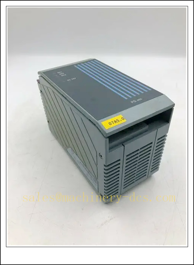
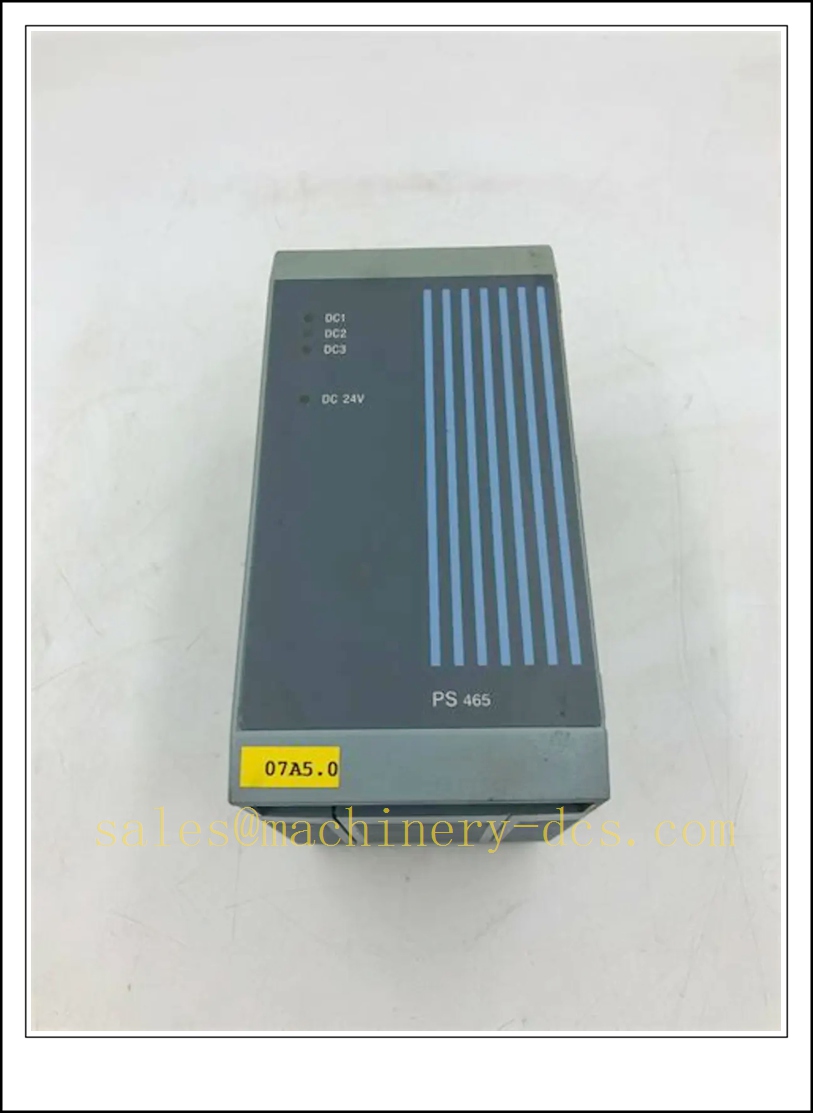
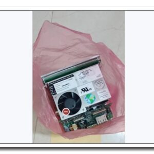
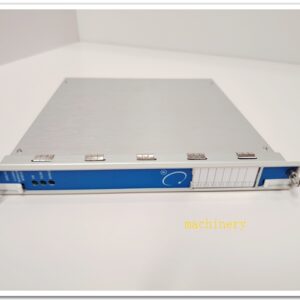
B&R 3PS465.9 Power Supply Module for System 2005 PLC Rack
Product Description
The 3PS465.9 is a rack power supply unit for B&R System 2005 automation racks. It converts an external 24 VDC input into stabilized internal backplane supply voltages to power the CPU, I/O modules and communication boards within the System 2005 chassis. This module provides overcurrent, overvoltage and short-circuit protection for the rack backplane, and features status LEDs for power good and fault indication. It supplies the required logic voltages for cyclic backplane communication and I/O signal processing. It is widely used as a spare and replacement part for legacy System 2005 machine control systems.
Technical Specifications
- Brand: B&R (Bernecker + Rainer)
- Part Number: 3PS465.9
- Series: System 2005
- Module Type: Rack Power Supply
- Input Voltage: 24 VDC (18…30 VDC operating range)
- Output: Stabilized internal rack voltages for System 2005 backplane
- Max Output Power: 100 W
- Protection: Overvoltage, overcurrent, short-circuit, reverse polarity
- Status Indicators: Power OK LED, Fault LED
- Cooling: Natural convection
- Operating Temperature: 0 °C ~ +60 °C
- Storage Temperature: -20 °C ~ +70 °C
- Relative Humidity: 5% ~ 95 %, non-condensing
- Mounting: Slot mount inside System 2005 rack
- Approximate Weight: 0.34 kg
- Compliance: CE, IEC 61131-2
3PS465.9
Application Scenarios
- Power supply for System 2005 CPU and I/O racks on injection molding machines
- Packaging machinery main control rack power source
- Textile machinery multi-axis controller rack powering
- Printing press control cabinet power feeding
- Material handling and palletizing automation control racks
- Water treatment PLC control cabinet power supply
- Retrofit and maintenance of existing B&R System 2005 installations
- Factory automation legacy control system spare replacement
8 Related B&R Model Recommendations
- 3CP360.60-1 – System 2005 Pentium CPU module
- 3AM051.6 – 4AI/4AO mixed analog I/O module
- 3CP260.60-1 – Mid-range System 2005 CPU
- 3DI476.6 – Digital input module
- 3DO480.6 – Digital output module
- 3IF613.9 – APCI communication interface module
- TB170 – Analog terminal block
- 0CFCRD.8192E.02 – CompactFlash memory card for CPU
Compatibility & Installation Pitfalls
Compatibility
- Developed exclusively for B&R System 2005 rack architecture; incompatible with X20, X67 or APROL platforms.
- Must be installed in the dedicated power supply slot of the System 2005 backplane.
- Total power consumption of all rack modules must not exceed the 100 W rating of 3PS465.9.
- Input source must be a regulated 24 VDC industrial power supply; unfiltered unstable DC may trigger under-voltage faults.
- Does not support hot-swap operation in most System 2005 configurations.
- Backplane hardware revision must match the module; older backplane versions may have connector or loading limitations.
Installation Pitfalls
- Disconnect the external 24 VDC source before removing or inserting the power supply module. Live insertion may damage backplane circuits.
- Observe polarity of the 24 VDC input terminals; reverse polarity will activate internal protection and can damage the unit.
- Calculate total rack load including CPU, I/O and APCI expansion modules to avoid continuous overload.
- Maintain clearance around the module for natural convection; enclosed tight cabinet spaces can cause over-temperature shutdown.
- Use properly sized, shielded 24 VDC supply cables; long thin cables create voltage drop under peak load.
- Do not mix different power supply types on the same System 2005 backplane.
- Check terminal screw torque for the 24 V input; loose connections produce intermittent power drops and random CPU resets.
- After replacement, verify all backplane voltages and confirm CPU and I/O modules boot normally.
Standard Operating Procedure (SOP)
SOP for 3PS465.9 Power Supply Module Inspection, Installation and Functional Test
- Pre-Installation Inspection Inspect the module casing, backplane connector and input terminals for physical damage, burn marks or contamination. Confirm part number 3PS465.9. Calculate total rack power load and verify compatibility with the System 2005 backplane and installed CPU/I/O set. Apply lockout-tagout to the external 24 VDC supply.
- Rack Installation Insert the 3PS465.9 into the dedicated power slot of the System 2005 rack and secure the latch. Terminate the 24 VDC input wiring at the module terminals. Route the main DC supply cable separately from high-power AC and inverter cables and implement proper cabinet grounding.
- Power-On Initial Check Release lockout-tagout and energize the 24 VDC source. Check the module Power OK LED. Confirm the CPU and all I/O modules power up without fault indicators. Access Automation Studio to verify backplane bus communication and module identification. Record supply voltage readings in the maintenance log.
- Load Test Run the rack under full static load, with all I/O modules powered. Trigger high-current conditions such as digital output switching and analog loop excitation. Monitor for voltage sag, fault LED activation or module shutdown. Confirm short-circuit protection operates correctly when simulated.
- Machine Commissioning Enable machine automatic sequences. Monitor supply stability during peak load events such as motion acceleration and valve actuation. Confirm power disturbances trigger controlled safe states instead of uncontrolled machine movement.
- Return to Service Clear fault indications and acknowledge diagnostic messages. Keep the rack under supervised operation and continuously monitor power status during the observation period. Notify operation staff that the 3PS465.9 power supply module is ready for normal production.
- Periodic Maintenance and Replacement During scheduled shutdown, inspect terminal tightness, cabinet temperature and LED status. Perform load voltage measurement under peak machine conditions. If the module shows persistent power loss or protection faults, isolate the 24 VDC supply before replacement. After installing the spare power supply, complete a full boot test, bus check and machine sequence test before releasing to production.

 Start Chat


 Send an Email


