
Description
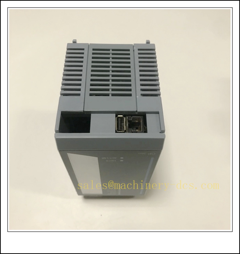
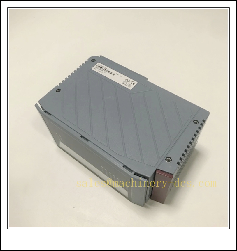
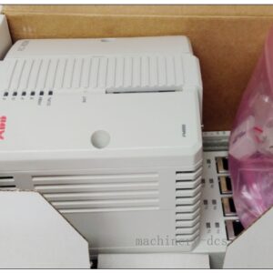
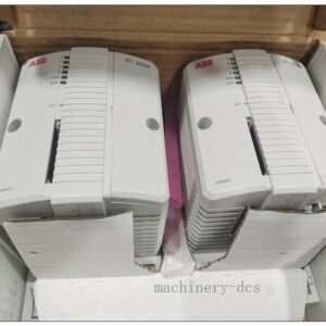
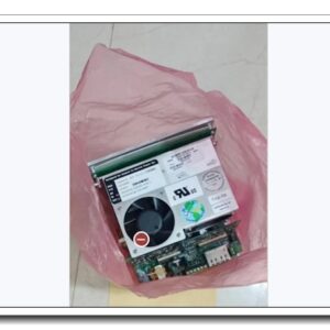
B&R 3CP360.60-1 Pentium 266 CPU Module for System 2005 PLC Rack
Product Description
The 3CP360.60-1 is a double-width central processing unit for the B&R System 2005 automation platform, powered by a Pentium 266 MHz processor with integrated floating-point unit. It executes real-time PLC logic, motion control and process regulation, and manages cyclic data exchange with local rack I/O modules over the System 2005 backplane bus. The unit features a CompactFlash slot for application program storage, an APCI expansion slot for optional communication adapters, plus built-in Ethernet, RS232 and USB 1.1 ports for programming, HMI and host communication. An on-board lithium battery preserves retentive variables and real-time clock during power loss. It is widely deployed as the main controller for legacy B&R machine automation systems and is a common spare for retrofit and maintenance projects.
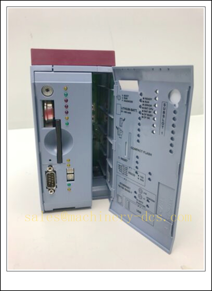
3CP360.60-1
Technical Specifications
- Brand: B&R (Bernecker + Rainer)
- Part Number: 3CP360.60-1
- Series: System 2005
- Module Type: CPU Controller (double slot width)
- Processor: Intel Pentium 266 MHz, with FPU
- Memory: 32 MB DRAM, 496 kB user SRAM; 256 kB retentive variable memory
- Cache: 2×16 kB L1 cache, 512 kB L2 cache
- Storage: CompactFlash slot (CF card sold separately)
- Expansion: 1×APCI slot for IF7xx communication modules
- Interfaces: 100BASE-T Ethernet, RS232 serial, USB 1.1
- Minimum task cycle: 400 µs
- Power Supply: 24 VDC; typical power consumption ~14 W (with CF and APCI module fitted)
- Status Indicators: RUN, FAULT, CPU, BUS, BAT, CF OK LEDs
- Backup: Internal lithium battery for RTC and remanent data
- Protection Class: IP20
- Operating Temperature: 0 °C ~ +60 °C
- Storage Temperature: -20 °C ~ +70 °C
- Relative Humidity: 5% ~ 95 %, non-condensing
- Mounting: Slot mounting inside System 2005 rack
- Approximate Weight: 0.55 kg
- Compliance: CE, IEC 61131-2
Application Scenarios
- Plastic injection molding machine main control and closed-loop motion regulation
- Packaging machinery multi-axis synchronization and recipe management
- Textile machinery tension control, cam profiling and sequence logic
- Material handling automated conveyor and palletizing control
- Water treatment plant sequence control and analog loop regulation
- Printing machinery register control and high-speed position synchronization
- Retrofit, spare replacement and migration preparation for legacy System 2005 installations
- General factory automation requiring deterministic real-time PLC and motion control
8 Related B&R Model Recommendations
- 3AM051.6 – Mixed 4AI/4AO analog I/O module
- 3CP260.60-1 – System 2005 mid-range CPU
- 3PS465.9 – System 2005 rack power supply
- 3DI476.6 – Digital input module
- 3DO480.6 – Digital output module
- TB170 – Analog signal terminal block
- 3IF613.9 – APCI communication interface module
- 0CFCRD.8192E.02 – Industrial CompactFlash memory card
Compatibility & Installation Pitfalls
Compatibility
- Designed exclusively for the B&R System 2005 rack family; not compatible with X20, X67 or APROL hardware.
- Requires System 2005 compatible firmware and Automation Studio versions matching the CPU generation.
- Application program must reside on a compatible industrial CompactFlash card; consumer CF cards may cause file corruption.
- APCI slot only supports B&R IF7xx series expansion modules; generic PCI devices cannot be used.
- Backplane slot assignment must match the hardware configuration; incorrect slot mapping prevents I/O communication.
- The CPU is not hot-swappable under normal System 2005 rack operation.
Installation Pitfalls
- De-energize the 24 VDC rack supply before inserting or removing the CPU; live insertion can damage the backplane bus.
- Handle CompactFlash cards carefully; power must be removed before card replacement to avoid program file loss.
- Check the lithium backup battery status regularly; expired battery causes loss of retentive variables and real-time clock.
- Separate Ethernet and serial signal cables from high-power inverter and motor wiring to avoid EMI-induced communication drops.
- Keep rack ventilation paths unobstructed; high cabinet temperature increases cycle jitter and triggers CPU overheat faults.
- Verify the APCI module is fully seated before power-up; loose APCI cards lead to intermittent communication failures.
- Save a full offline backup of the project, including hardware configuration and recipe data, before CPU replacement.
- After replacement, the new CPU will not retain the application; the project must be downloaded from Automation Studio.
Standard Operating Procedure (SOP)
SOP for 3CP360.60-1 CPU Module Inspection, Installation and Functional Test
- Pre-Installation Inspection Examine the module housing, backplane connector and CF socket for physical damage, bent pins or contamination. Confirm part number 3CP360.60-1. Verify compatibility with the System 2005 rack, I/O modules, APCI card, CF memory and Automation Studio project version. Review machine control drawings and lockout-tagout the rack 24VDC supply.
- Rack Installation Insert the 3CP360.60-1 into the designated double-width rack slot and secure the latch. Fit the CompactFlash card and APCI expansion module if used. Terminate Ethernet, RS232 and USB connections. Route communication cables separately from high-energy power wiring and apply EMC grounding per B&R specifications.
- Project Download and Configuration Restore rack 24 VDC power. Connect Automation Studio online to the CPU. Confirm hardware identification, backplane bus and APCI module recognition. Download the validated project, hardware configuration and I/O mapping to the CompactFlash storage. Save a full project backup offline. Resolve bus, battery or CF card alarms before machine testing.
- I/O and Communication Test Execute manual point test for digital and analog I/O modules. Verify Ethernet HMI connection, serial communication and APCI interface exchange. Monitor task cycle times, CPU load and bus status in the diagnostic menu. Inject simulated I/O faults to confirm alarm handling and safe program behaviour. Record cycle performance and diagnostic response in the test log.
- Machine Commissioning Release field circuit isolation only after point-level testing passes. Run automatic sequences, motion profiles and closed-loop control under low-speed test conditions. Gradually ramp to rated operating speed and load. Confirm fault conditions trigger predefined safe states rather than uncontrolled motion. Cross-check HMI alarms and remote host data exchange.
- Return to Production Reset fault latches and acknowledge diagnostic messages. Remove lockout-tagout. Monitor CPU load, bus health, battery voltage and CF status during the supervised observation window. Notify operations that the 3CP360.60-1 CPU is commissioned and ready for automatic production operation.
- Periodic Maintenance and Replacement During scheduled downtime, inspect rack cooling, connector condition and battery health. Run the project’s I/O proof-test and communication verification routines. If persistent unrecoverable CPU or bus faults occur, lock out rack power before replacement. After fitting the spare CPU, reload the project, recheck I/O mapping and complete full sequence and motion test before releasing the machine online.

 Start Chat


 Send an Email


