
Description
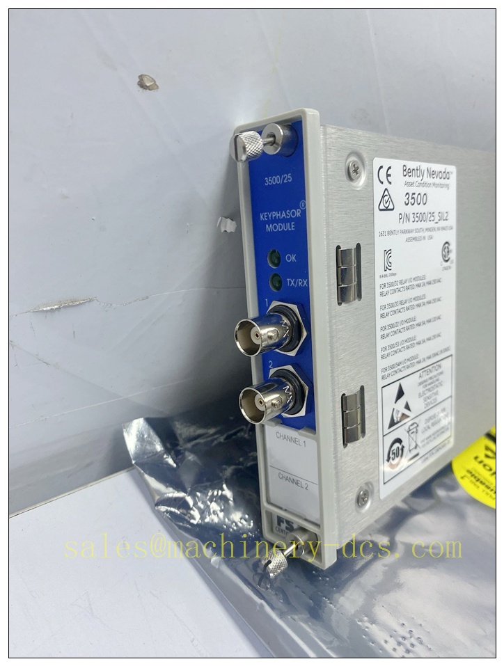
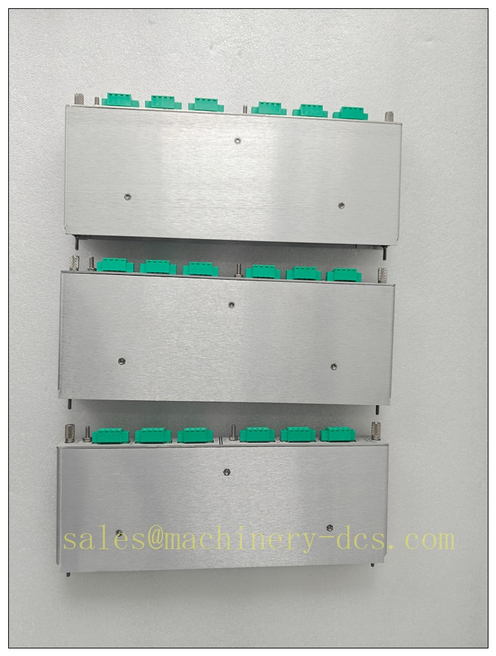
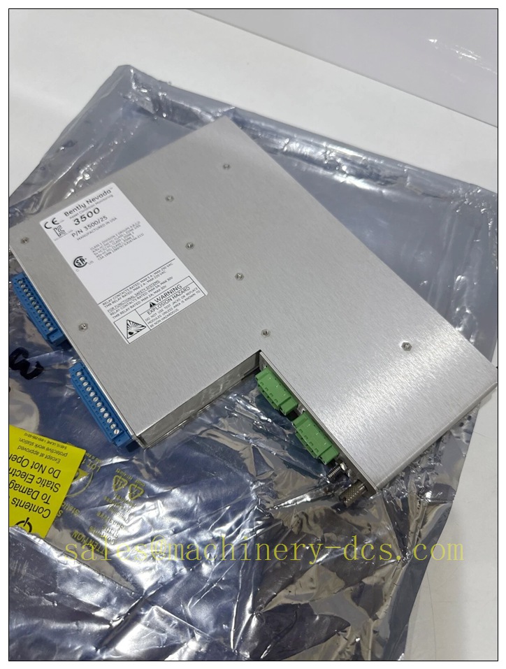
Bently Nevada 3500/25 SIL2-01-01-00 2-Channel SIL 2 Enhanced Keyphasor Module for 3500 Machinery Protection Rack
Product Description
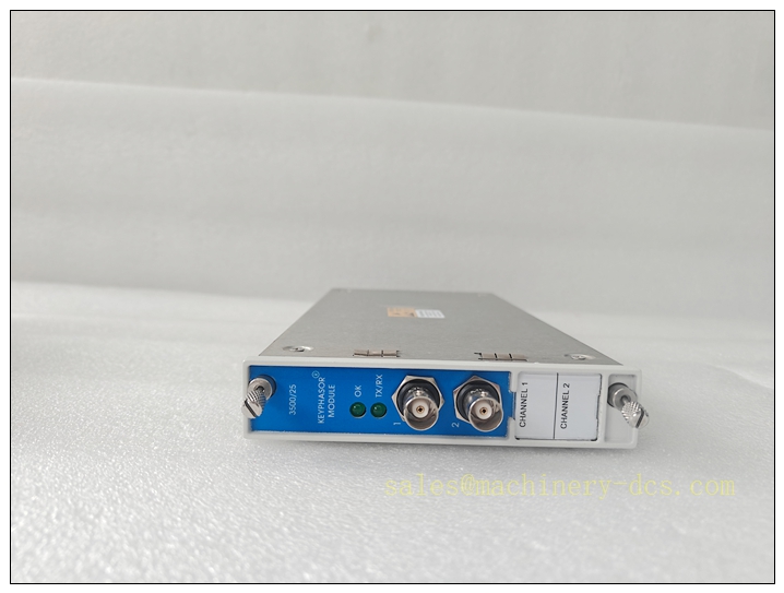
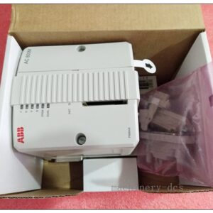
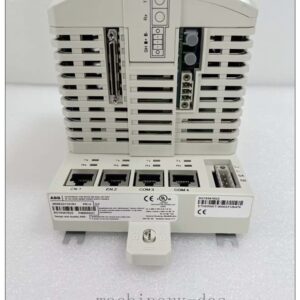
The 3500/25 SIL2-01-01-00 is a half-height, dual-channel enhanced Keyphasor module within the Bently Nevada 3500 TSI machinery protection platform, certified to IEC 61508 SIL 2 for safety-related rotating machinery protection functions. It accepts pulse signals from proximity probes or magnetic pickup transducers mounted on rotating shafts, and conditions raw trigger pulses into precise digital Keyphasor timing references. This once-per-turn or multi-event-per-turn timing signal is distributed across the rack backplane to paired monitor modules such as vibration, thrust and speed monitors. The Keyphasor reference enables accurate rotational speed calculation, 1X phase measurement, orbit plotting, and transient vibration diagnostics for turbine and compressor rotors. Two buffered Keyphasor outputs are available via front-panel coaxial connectors and rear terminal blocks for external diagnostic tools. Continuous on-board diagnostics detect transducer open circuits, short circuits, low signal amplitude and loss of trigger pulses to support SIL 2 fault detection requirements. It communicates status and timing data over the internal 3500 rack bus to the Rack Interface Module and configuration software.
3500/25 SIL2-01-01-00
Technical Specifications
- Brand: Bently Nevada
- Model: 3500/25 SIL2-01-01-00
- Form Factor: Half-height, 2 independent Keyphasor channels
- Safety Rating: SIL 2 (IEC 61508)
- Transducer Input: Eddy current proximity probe, magnetic pickup
- Input Impedance: 25 kΩ
- Trigger Modes: Auto threshold / Manual threshold with configurable hysteresis
- Frequency / Speed Range: 1 rpm up to 20 kHz (1–1,200,000 CPM)
- Transducer Excitation: -24 VDC, max 40 mA per channel
- Buffered Outputs: 2 front BNC, 2 rear terminal buffered Keyphasor signals
- Output Impedance: Max 504 Ω
- Diagnostics: Loss of trigger, wire break, short circuit, signal amplitude fault, module self-test
- Rack Communication: 3500 series backplane bus
- Operating Temperature: 0 °C to +60 °C
- Storage Temperature: -40 °C to +85 °C
- Relative Humidity: 5% to 95% non-condensing
- Configuration Software: Bently Nevada 3500 Rack Configuration Software
- Power Source: Powered from 3500 rack backplane, supplied by 3500/15 power modules
- Typical Power Consumption: 6.5 W
Application Scenarios
- Steam turbine and gas turbine rotor phase reference and overspeed monitoring
- Centrifugal compressor and axial compressor vibration phase measurement
- Generator large rotating machinery TSI protection and transient diagnostics
- Petrochemical and refinery SIL 2 machinery safety instrumented functions
- Onshore and offshore oil & gas production compressors and high-speed pumps
- Industrial fan and blower rotor imbalance, misalignment and rub diagnostics
- System 1 condition monitoring for orbit, polar plot and transient event capture
- Hazardous Class I Div 2 / Zone 2 turbine supervisory instrumentation racks
8 Related Bently Nevada Model Recommendations
- 3500/42 SIL-01-00 – 4-Channel SIL 2 Vibration & Position Monitor
- 3500/40M – 4-Channel Speed / Overspeed Monitor
- 3500/33 SIL201-00 – 4-Channel SIL 2 Relay Output Module
- 3500/15-05-05 – Dual AC Redundant Rack Power Supply
- 3500/20 – Rack Interface Module (RIM)
- 3500/92 – Communication Gateway Module
- 3500/05 – 3500 Series Rack Chassis Assembly
- 3500/25 Non-SIL Version – Standard Enhanced Keyphasor Module
Compatibility & Installation Pitfalls
Compatibility
- Designed exclusively for the Bently Nevada 3500 rack backplane; incompatible with older 3300 racks.
- Half-height design; two 3500/25 modules may occupy one full-height rack slot.
- Requires compatible RIM firmware and 3500 configuration software to maintain SIL 2 certification.
- Provides timing reference for 3500/42, 3500/40M and other monitor modules; it does not directly execute trip logic.
- SIL-rated 3500/25 may coexist with non-SIL modules in the same rack, but safety SIF loops must use only SIL-qualified hardware.
- Verify transducer type and cable length settings; magnetic pickups and proximity probes require different conditioning parameters.
Installation Pitfalls
- Do not hot-swap this module while it provides the sole Keyphasor reference for an active SIL overspeed or vibration protection loop; loss of timing reference can invalidate trip measurements.
- Keyphasor transducer cables must be routed separately from VFD and high-current AC cables; induced noise can create false trigger pulses and incorrect speed/phase readings.
- Incorrect target geometry or excessive probe gap will cause intermittent trigger dropout; confirm gap voltage and target tooth/keyway dimensions before commissioning.
- When used in SIL 2 safety functions, the loss-of-Keyphasor diagnostic alarm must be configured; missing fault voting may hide transducer degradation.
- Buffered BNC outputs on the front panel are for diagnostics only; do not use these signals for safety trip logic.
- Ground loops on probe cabling distort trigger thresholds; apply single-point shield grounding at the rack end only.
- Auto threshold mode has a minimum 2 Vpp trigger requirement; low-amplitude magnetic pickup signals require manual threshold configuration.
- A healthy “OK” LED does not confirm valid shaft timing; phase and speed must be validated by running rotor tests or signal injection.
3500/25 SIL2-01-01-00
Standard Operating Procedure (SOP)
SOP for 3500/25 SIL2-01-01-00 Keyphasor Module Installation, Configuration and Functional Test
- Pre-Installation Inspection Inspect the module for physical damage, connector pin damage or contamination. Confirm the full part number and SIL marking match project safety specifications. Review transducer type, probe gap setting, target geometry and safety loop logic. Apply lockout-tagout to associated machinery trip circuits before rack work commences.
- Rack Installation Power down the rack if the module supplies the only Keyphasor signal for an active SIL protection loop. Insert the half-height 3500/25 SIL2-01-01-00 into the designated half-slot position and secure the retaining screw. Terminate proximity or magnetic pickup wiring to the rear terminal assembly. Separate low-level transducer cables from high-power circuits and implement shielding per approved safety drawings.
- Software Configuration Launch the 3500 rack configuration software and read the existing rack setup. Add the Keyphasor module to the rack slot map. Select transducer type, auto or manual trigger threshold, hysteresis and fault detection parameters. Assign each Keyphasor channel to the corresponding speed and vibration monitor channels that require phase reference. Download the validated configuration to the rack and resolve all configuration fault codes. Archive the safety configuration file for IEC 61508 audit traceability.
- Transducer Loop Calibration and Trigger Test Set and verify probe gap voltage for eddy current Keyphasor probes. Run static and dynamic signal injection to simulate shaft trigger pulses. Confirm the module detects pulses and transmits valid speed and timing reference to paired monitor modules. Simulate wire break and short-circuit conditions to verify loss-of-trigger diagnostics activate as configured. Check front-panel buffered outputs using oscilloscope if required for diagnostic verification.
- Rotating Functional Verification With the machine available for slow roll or run-up, start rotation and confirm stable speed readings and consistent 1X phase values on associated vibration monitors. Confirm no intermittent trigger dropout or phase jump events. Validate that loss-of-Keyphasor faults propagate correctly to alarm and voting logic in the safety loop. Record all speed, phase and diagnostic test results in the functional safety test log.
- Return to Service Clear all temporary test alarms and fault latches. Remove lockout tags and restore the machinery protection loop to online status. Monitor Keyphasor health, speed and phase readings for the required observation period to confirm stable operation with no intermittent faults. Notify operations that phase and speed reference functions are active.
- Periodic Maintenance and Replacement During planned outages, inspect probe mounting, target condition, cable terminations and shielding integrity. Re-test trigger detection and fault diagnostics per the site SIF proof-test schedule. If the module reports persistent unrecoverable diagnostics, isolate the safety loop before replacement. After installing a spare module, reload the validated configuration, re-calibrate transducer settings and repeat the full trigger and rotating functional test before returning to protection duty.

 Start Chat


 Send an Email


