
Description
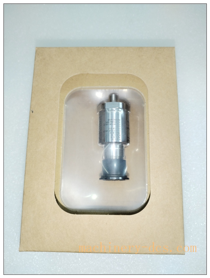
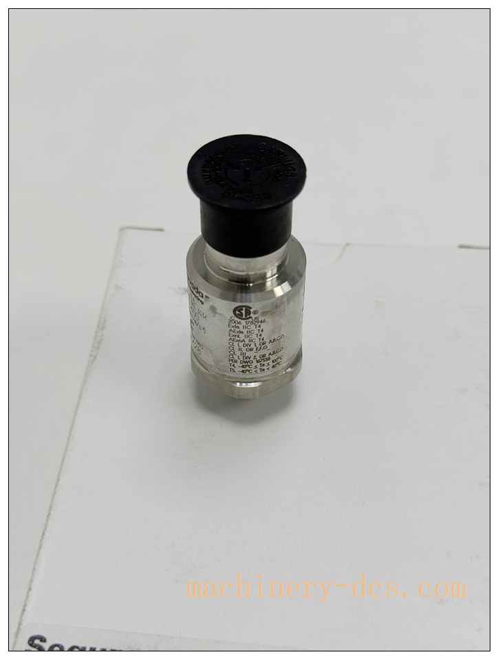
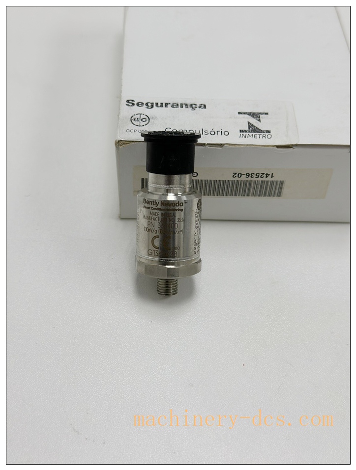
Bently Nevada 330400-02-05-00 Piezoelectric Accelerometer Vibration Sensor
Meta Description
Bently Nevada 330400-02-05-00 is an API 670 compliant three-wire piezoelectric accelerometer with integrated M8×1 mounting stud and CSA hazardous area certification. Featuring 100 mV/g standard sensitivity, 10 Hz–15 kHz wide frequency response and −24 V DC powered internal charge amplifier, this industrial vibration sensor delivers high-precision casing vibration monitoring for turbines, compressors, gearboxes and other critical rotating machinery, fully compatible with Bently Nevada 3300 and 3500 series monitoring systems.
Product Core Overview
The 330400-02-05-00 is a high-performance industrial piezoelectric accelerometer developed by Bently Nevada (Baker Hughes), specially engineered for casing-mounted dynamic vibration measurement of critical industrial equipment. Integrated with a built-in charge amplifier, this three-wire sensor eliminates external signal amplification equipment, ensuring stable and low-noise vibration signal output in harsh industrial environments.
Configured with an integral M8×1 threaded mounting stud and certified for CSA hazardous area operation, the unit fully meets API 670 international machinery monitoring standards. It accurately captures high-frequency vibration signatures including gear mesh vibration, bearing fault vibration and structural resonance vibration within 10 Hz to 15 kHz bandwidth. With a rugged fully sealed metal housing, excellent temperature resistance and mechanical shock resistance, it is widely applied in power generation, petrochemical, metallurgy and process manufacturing industries, providing reliable vibration data for equipment condition monitoring, fault early warning and predictive maintenance.
330400-02-05
Key Technical Specifications
| Technical Item | Specific Parameters |
|---|---|
| Part Number | 330400-02-05-00 |
| Sensor Type | Three-wire piezoelectric accelerometer with internal charge amplifier |
| Mounting Configuration | Integral M8×1-6g threaded stud (02 code) |
| Certification | CSA Hazardous Area Approval (05 code) |
| Standard Sensitivity | 100 mV/g (10.2 mV/m/s²), tolerance ±5% @ 100 Hz |
| Peak Acceleration Range | 50 g (490 m/s²) peak |
| Frequency Response | 10 Hz ~ 15 kHz, ±3 dB flat response |
| Amplitude Linearity | ±1% maximum error up to 50 g peak |
| Broadband Noise Floor | 0.004 g rms (10 Hz–15 kHz) |
| Power Supply Requirement | −24 V DC (standard Bently monitoring system power supply) |
| Operating Temperature Range | −55°C ~ +121°C (−67°F ~ +250°F) |
| Connector Type | 3-pin threaded female connector |
| Industry Compliance | Fully compliant with API 670 standard |
| Resonance Frequency | >15 kHz (avoid resonant frequency operation) |
Quality Control Procedures
All 330400 series accelerometers undergo strict full-process factory quality inspection and calibration to ensure consistent precision, stability and compliance with industrial standards:
- Incoming Visual & Traceability Inspection: Each unit is visually inspected for housing integrity, thread condition, connector finish and label completeness. Unique serial number registration is performed to establish full lifecycle traceability for batch management and after-sales service.
- Precision Sensitivity Calibration: Professional vibration shaker platform is used for fixed-point calibration at 100 Hz reference frequency. The output sensitivity is verified to ensure strictly within ±5% tolerance, with calibration data permanently recorded and bound to the device serial number.
- Full-Band Frequency Response Testing: Automated frequency sweep test from 10 Hz to 15 kHz is implemented to confirm the amplitude response meets ±3 dB bandwidth specification, eliminating frequency attenuation and signal distortion defects.
- Electrical Performance Verification: Comprehensive electrical tests including power supply adaptability, DC bias output stability, circuit continuity and insulation resistance are conducted to ensure no short circuit, open circuit or electrical interference risks.
- Environmental Adaptability Screening: Simulated industrial temperature cycling and mild mechanical shock tests are performed to verify structural stability and electrical performance consistency in complex working conditions.
- Housing Sealing & Protection Test: Air tightness and waterproof sealing inspection ensures the sealed housing effectively resists dust, moisture and corrosive gas ingress, adapting to harsh field environments.
- Final Configuration & Document Validation: Double-check product configuration codes (mounting thread, hazardous area certification). Qualified products are issued with official calibration certificates and inspection reports, with all data archived for factory release.
Recommended Compatible Models & Accessories
Alternative Sensor Models
- 330400-01-05-00: Equivalent electrical performance and CSA certification, equipped with 1/4-28 UNF integral stud, suitable for equipment with imperial thread mounting holes.
- 330400-02-00-00: M8×1 stud version without hazardous area certification, cost-effective for conventional non-explosive industrial environments.
- 330425-02-05-00: High-range vibration monitoring variant, 25 mV/g low sensitivity, 75 g peak measurement range, ideal for heavy-shock and high-amplitude vibration equipment.
Matching System & Accessories
- Compatible Monitoring Modules: 3500/42 Accelerometer Monitor, 3300/25 Peak Acceleration Monitor, 3300/26 RMS Acceleration Monitor
- Special Interconnect Cables: 130539 standard shielded cable, 16710 armored anti-interference cable, maximum supporting cable length of 30 meters
Frequently Asked Questions (FAQ)
Q1: What power supply does the 330400-02-05-00 require?
A: The sensor requires a standard −24 V DC power supply to drive the internal charge amplifier, which is uniformly provided by Bently Nevada 3300/3500 series monitoring racks. External non-standard power supplies are not recommended to avoid signal noise and measurement deviation.
Q2: Can this accelerometer measure shaft relative vibration?
A: No. This is a casing vibration measurement sensor, designed for housing and structural acceleration vibration monitoring. For shaft relative vibration and rotor displacement measurement, please select Bently Nevada 3300XL series proximity probes.
Q3: What are the risks of incorrect mounting torque?
A: Insufficient torque will cause poor vibration coupling, attenuate high-frequency signals and reduce measurement accuracy; excessive torque will damage the M8×1 stud thread and sensor base structure, leading to permanent failure. Strictly follow the standard torque specification during installation.
Q4: What is the maximum allowable cable transmission distance?
A: With original factory shielded cables, the maximum transmission length is 30 meters. Non-original third-party cables will introduce electromagnetic interference, reduce bandwidth and affect vibration signal fidelity.
Q5: Is this sensor applicable for explosive hazardous areas?
A: Yes. The 330400-02-05-00 carries valid CSA hazardous area certification. Users shall comply with local hazardous area classification standards and explosion-proof wiring specifications for installation and operation.
Q6: Can the sensor be disassembled and repaired on site?
A: No. The sensor is an integrated sealed factory-calibrated component. Unauthorized disassembly will damage the sealing structure, void certification validity and calibration accuracy. Damaged or faulty units must be returned to official authorized service centers for maintenance and recalibration.
330400-02-05
Installation & Configuration Guide
1. Pre-Installation Preparation
- Inspect the sensor for transit damage, confirm the part number, serial number and thread integrity match the order requirements.
- Process a flat, smooth and rigid mounting surface on the equipment bearing housing or casing, remove paint, rust, oil stains and debris to ensure tight fitting. The mounting hole must be perpendicular to the equipment surface within ±6 arc-minutes.
- Check the compatibility of the 3500/3300 series monitoring module and prepare factory-matched shielded cable.
2. Mechanical Mounting Instructions
- Apply a thin layer of high-temperature vibration coupling grease (Dow Corning 340 or equivalent) on the sensor base to optimize high-frequency vibration transmission efficiency.
- Screw the integrated M8×1 stud into the reserved mounting hole, tighten with a standard torque of 6.8±1.4 N·m (60±12 in-lb). Avoid over-tightening or loose mounting.
- Fix the cable with a clamp to prevent tensile stress, bending torque and vibration impact from being transmitted to the sensor connector.
3. Electrical Wiring Specification
- Hand-tighten the threaded connector between the sensor and the interconnect cable to ensure reliable shielding and tight connection.
- Standard terminal wiring definition: Cable A=Signal, Cable B=−24 V DC Power, Cable C=Common Ground
- Ground the cable shield strictly in accordance with site specifications to avoid multi-point grounding loops and eliminate electromagnetic noise interference.
- Perform continuity and short-circuit inspection before power-on to ensure safe circuit operation.
4. System Configuration & Commissioning
- Power on the monitoring rack, check the channel DC bias voltage to confirm normal sensor power supply and working status.
- Set channel parameters: input type=accelerometer, fixed sensitivity=100 mV/g, measurement range=0–50 g peak.
- Complete field tap/bump test: gently tap the sensor housing, verify real-time vibration data response is normal, confirm signal acquisition and system linkage are effective before formal commissioning and operation.

 Start Chat


 Send an Email


