
Description
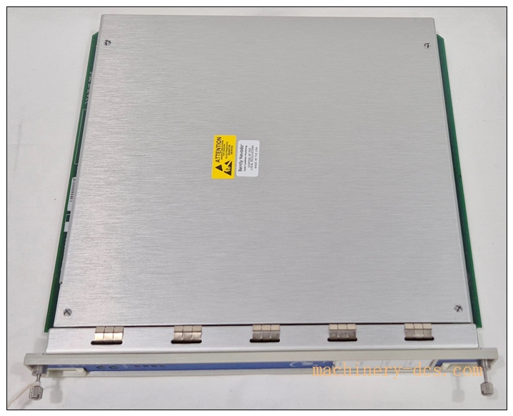
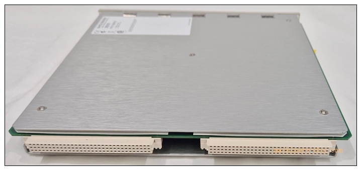
Bently Nevada 149986‑02 (3500/20 Rack Interface Module)
Title
Bently Nevada 149986‑02 3500/20 Rack Interface Module for 3500 Machinery Protection System
Meta‑Description
Bently Nevada 149986‑02 is the 3500/20 rack interface module, acting as central backplane bus coordinator for the 3500 machinery‑protection rack. It manages inter‑module communication, synchronizes system data, provides system timing and fault detection, mandatory for 3500/92 communication gateway operation, API‑670 compliant for turbine and compressor protection racks.
Product Core Overview
149986‑02 is the hardware part number for Bently Nevada 3500/20 Rack Interface Module, the system‑level coordination core of the entire 3500 machinery‑protection rack. Installed in the fixed dedicated slot of the 3500 rack, it governs all internal backplane bus traffic between monitor modules, power supplies and communication gateway modules.
This module synchronizes measurement sampling timing, collects module health status, handles system fault detection, manages non‑volatile memory for storing rack‑wide configuration and alarm parameters. It serves as the essential bridge between monitor cards (3500/40M, 3500/42M etc.) and the 3500/92 communication gateway. Without a functional 3500/20 module, the communication gateway cannot retrieve data from monitor channels, and partial system diagnostic functions will be unavailable. Hot‑swap capable, it supports online replacement without rack power‑down. Widely used in power generation, petrochemical and oil‑gas rotating‑equipment protection systems for turbines, compressors and generators.
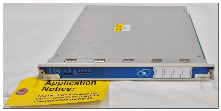
350032M 149986‑02
Main Technical Specifications
| Item | Parameter |
|---|---|
| Part Number | 149986‑02 (3500/20 Rack Interface Module) |
| Module Type | Rack Interface & Bus Coordinator Module |
| Compatible System | Bently Nevada 3500 series machinery protection rack |
| Power Source | Backplane powered by 3500 rack power supply; typical 6.2 W consumption |
| Hot‑Swap Support | Yes, hot‑swappable |
| Core Functions | Backplane bus management, system time synchronization, rack‑wide configuration storage, module health monitoring, fault diagnostics, data forwarding to communication module |
| LED Indicators | OK, System Fault, Bypass Status |
| Operating Temperature | 0 °C ~ +65 °C |
| Storage Temperature | −40 °C ~ +85 °C |
| Relative Humidity | 5 %‑95 % non‑condensing |
| Compliance | API‑670, CE, UL/cULus safety certifications |
| Installation | Dedicated fixed slot within 3500 rack |
Quality Control Procedures
- Visual & Mechanical Incoming Inspection: Inspect PCB components, front‑panel hardware, connectors and label printing. Serial number is recorded for full‑lifecycle traceability.
- Backplane Connector Integrity Test: Check pin continuity, insulation and isolation performance of rack backplane interface connector.
- Bus‑Coordination Functional Test: Simulate multiple monitor modules plugged into rack slots; verify backplane bus scheduling, data collection and timing‑synchronization functions.
- Non‑volatile Memory Validation: Write‑read‑erase full rack configuration data, confirm stable storage of channel parameters, alarm setpoints and system settings.
- System‑Fault Logic Test: Inject simulated module‑fault, power‑supply‑fault and bypass‑state signals; verify LED indication and fault‑status reporting.
- Gateway‑Interface Compatibility Test: Cooperate with 3500/92 communication module to validate normal data forwarding between monitor cards and gateway.
- Environmental Stress Screening: Temperature‑cycle test within full operating temperature range to verify thermal stability.
- EMC Performance Test: Simulate industrial cabinet electromagnetic interference environment.
- Final End‑of‑Line Validation & Archiving: Complete full‑function test suite; all test records are archived bound to unit serial number before factory release.
Related Brand Model Recommendations
- 149986‑01: Older hardware revision of 3500/20 rack interface module.
- Matching Communication Module: 136180‑01 (3500/92 Communication Gateway).
- Matching Monitor Modules: 176449‑01 (3500/40M), 176449‑02 (3500/42M).
- System Accessories: 3500 rack power supply units, monitor input transducer assemblies.
Frequently Asked Questions (FAQ)
Q1: What will happen if 3500/20 (149986‑02) fails? A: Backplane bus coordination stops. 3500/92 communication gateway loses access to all monitor‑channel data. Rack‑saved configurations cannot be read. Monitor modules may still execute local protection alarm logic, but system‑level diagnostics and host data export will fail.
Q2: Does this module support hot‑swap? A: Yes. Hot‑swap is supported. It can be replaced while the 3500 rack remains powered. All rack‑wide configurations are stored inside this module and will not be lost during replacement.
Q3: Can the 3500 system run without 3500/20 module? A: Partial‑function operation only. Individual monitor modules may perform local protection, but system‑wide data collection, event logging and communication‑gateway data output are unavailable. Normal complete‑system operation requires 3500/20.
Q4: Where are channel alarm setpoints stored? A: All rack‑level configuration, channel parameters and alarm setpoints are stored in the non‑volatile memory on the 3500/20 rack interface module.
Q5: Does 149986‑02 process transducer vibration signals? A: No. It is purely a system‑bus coordination module. Vibration‑signal acquisition and calculation are completed by individual monitor modules such as 3500/40M and 3500/42M.
Q6: Can I repair this module on‑site? A: No. Unauthorized disassembly voids certification and warranty. Return defective units to authorized service centre.
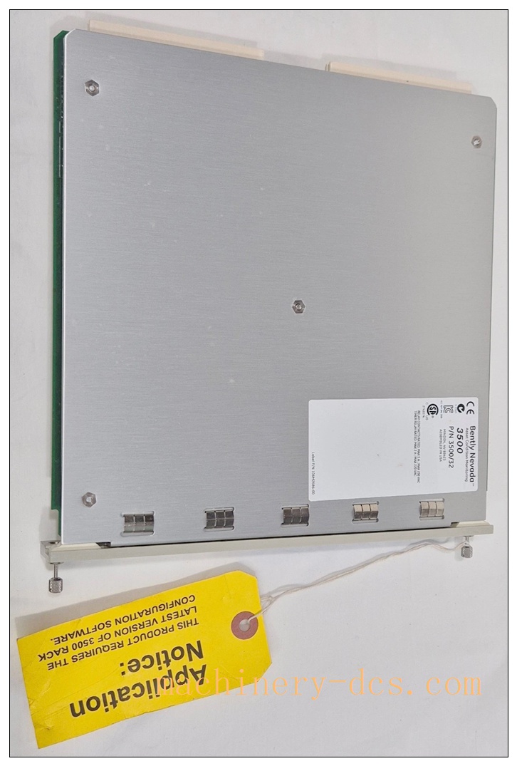
350032M 149986‑02
Installation & Configuration Guide
Pre‑Installation
- Inspect module for transit damage. Confirm part number 149986‑02 and serial‑number match purchase order.
- Confirm 3500 rack power supply works properly. Prepare other target monitor modules and communication gateway module.
- Confirm the dedicated fixed slot for rack‑interface module on the 3500 rack chassis.
Mechanical Installation
- Insert 149986‑02 into the dedicated rack‑interface slot, push firmly until backplane connector fully seats. Tighten front‑panel captive screws.
Hot‑swap is allowed; rack power can remain active during replacement.
Electrical Wiring
- No external field‑signal wiring required for this module. It communicates exclusively via rack internal backplane bus.
- Ensure rack chassis good grounding is completed per site specification.
System Configuration & Commissioning
- After module installation, power‑on the rack. Observe front‑panel LED indicators: OK LED should illuminate normally; no System‑Fault alarm.
- Connect 3500 configuration software to 3500/92 communication gateway. Read existing rack configuration stored inside 3500/20 module.
- If it is a brand‑new blank module, download complete rack configuration file into 3500/20 non‑volatile memory.
- Verify all plugged‑in monitor modules are correctly recognized by the rack system. Check system‑diagnostic status without system‑level fault reports.
- Complete full‑system commissioning together with communication gateway and monitor channels. Save backup copy of rack‑configuration file.

 Start Chat


 Send an Email


