
Description
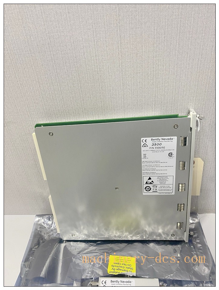
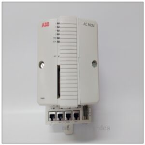
Bently Nevada 136180‑01 (3500/92 Communication Gateway Module)
Title
Bently Nevada 136180‑01 3500/92 Communication Gateway Module for 3500 Machinery Protection Rack
Meta‑Description
Bently Nevada 136180‑01 (3500/92) is a hot‑swappable communication gateway module for the 3500 machinery protection system. It provides Ethernet 10BASE‑T and serial RS‑232/422/485 interfaces, supports Modbus TCP / Modbus RTU, exports real‑time measurement values, alarm status and event logs to DCS, SCADA and System‑1 software, compliant with API‑670 for turbine and compressor protection systems.
136180‑01
Product Core Overview
136180‑01 is the hardware part number for Bently Nevada 3500/92 Communication Gateway Module, a core communication interface unit for the 3500 rack‑based machinery protection system. Installed in the dedicated communication slot of 3500 rack, it acquires all channel measurement data, alarm status, module health information and sequence‑of‑events logs from the rack backplane bus.
This gateway converts internal rack‑bus data into standard industrial communication protocols for third‑party host integration. Front‑panel RJ45 Ethernet port supports BNC host protocol for 3500 configuration software and System‑1 diagnostic platform, alongside Modbus‑TCP for DCS/SCADA connection. Rear terminal block delivers RS‑232/422/485 serial communication with Modbus RTU / ASCII support. Flexible Modbus register mapping allows users to select required measurement points, alarm flags and diagnostic status. Hot‑swap capability enables online replacement without rack power‑down. Widely deployed in power generation, petrochemical and oil‑gas plants to connect turbine, compressor and generator protection racks to plant‑wide control systems.
Main Technical Specifications
| Item | Parameter |
|---|---|
| Part Number | 136180‑01 (3500/92) |
| Module Type | Communication Gateway Module |
| Compatible System | Bently Nevada 3500 series machinery protection rack |
| Power Supply | Backplane powered from 3500 rack; typical 5.0‑5.6 W power consumption |
| Hot‑Swap Support | Yes, hot‑swappable, no rack power shutdown required |
| Front‑Panel Interface | RJ‑45 10BASE‑T Ethernet (IEEE802.3) |
| Rear‑Side Serial Interface | RS‑232 / RS‑422 / RS‑485 |
| Supported Protocols | BNC Host Protocol, Modbus TCP, Modbus RTU, Modbus ASCII, DNP3 |
| Data Refresh Rate | ≤ 1 second for full‑rack data collection |
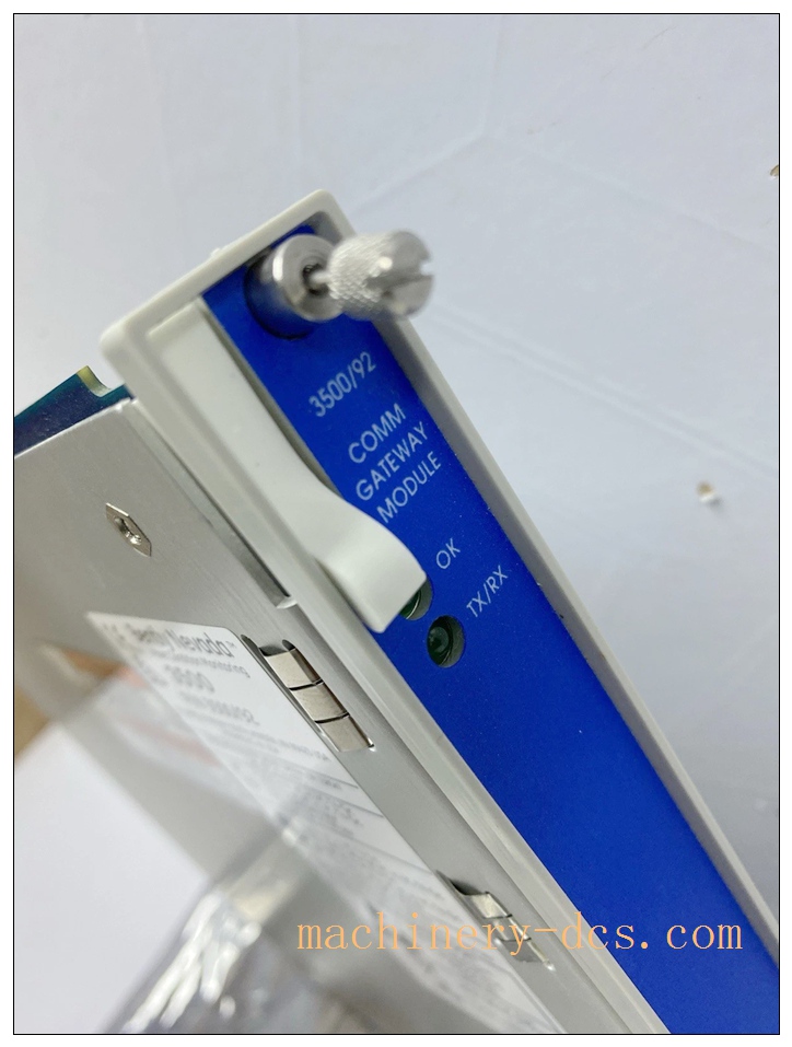
| Front‑Panel LED Indicators | OK (module health), TX/RX (bus communication activity) |
| Operating Temperature | 0 °C ~ +65 °C |
| Storage Temperature | −40 °C ~ +85 °C |
| Relative Humidity | 5 %‑95 % non‑condensing |
| Compliance | API‑670, CE, UL/cULus safety certifications |
| Physical Dimension | 241 mm × 24.4 mm × 242 mm |
| Weight | Approx. 0.82 kg |
Quality Control Procedures
- Visual & Mechanical Incoming Inspection: Visual inspection of PCB assembly, front‑panel hardware, connectors and serial‑number marking. Serial number recorded for full‑lifecycle traceability.
- Backplane Interface Continuity Test: Verify pin integrity, continuity and isolation for rack backplane connector.
- Communication Port Functional Test: Full validation of Ethernet and serial port hardware; test communication handshake under multiple protocol modes.
- Data‑Acquisition Validation: Simulate rack‑bus data traffic to verify reading of measurement values, alarm states and event logs. Validate configurable Modbus register mapping function.
- Fault‑Diagnostic Logic Test: Inject simulated internal faults to confirm correct OK‑LED status reporting and fault‑code output.
- Environmental Stress Screening: Temperature‑cycle test across full operating temperature range for thermal stability verification.
- EMC Interference Test: Simulate cabinet‑level electromagnetic noise to guarantee stable communication performance.
- Final End‑of‑Line Validation & Archiving: Complete full‑function test suite; all test records archived bound to unit serial number before factory release.
Related Brand Model Recommendations
- 3500/90: Legacy communication gateway module, limited register‑mapping flexibility, phased‑out replacement target for 3500/92.
- Matching Rack Component: 3500/20 Rack Interface Module (mandatory for 3500/92 operation).
- Associated Monitor Modules: 176449‑01(3500/40M), 176449‑02(3500/42M).
- Accessories: CAT5e Ethernet cable, 139036‑01 serial Y‑cable, RS232‑to‑RS485 converter.
- Host Software: 3500 Configuration Software, Bently Nevada System‑1 Condition Monitoring Software.
Frequently Asked Questions (FAQ)
Q1: Is 3500/20 rack interface module required for 136180‑01 operation? A: Yes. The 3500/20 Rack Interface Module must be installed in the rack; otherwise the 3500/92 cannot access back‑plane bus data.
Q2: Does this gateway support hot‑swap? A: Yes. Hot‑swap is supported. Module can be inserted or removed while 3500 rack remains powered. Communication configuration parameters are stored in rack non‑volatile memory.
Q3: What data can be exported via Modbus? A: Real‑time measured values, Alert/Danger alarm status, channel fault status, module health status, bypass status and partial sequence‑of‑event information. User‑customizable Modbus register mapping is supported.
Q4: Can 136180‑01 directly connect to vibration sensors? A: No. It is purely a communication gateway. It does not process raw transducer signals. All measurement data comes from monitor modules over the rack back‑plane bus.
Q5: Can I use both Ethernet and serial ports at the same time? A: Yes. Ethernet and serial interfaces can run simultaneously for dual‑host connection scenarios.
Q6: Is on‑site repair permitted? A: No. This is factory‑calibrated integrated PCB assembly. Unauthorized disassembly voids certification and warranty. Return defective units to authorized service centre.
136180‑01
Installation & Configuration Guide
Pre‑Installation
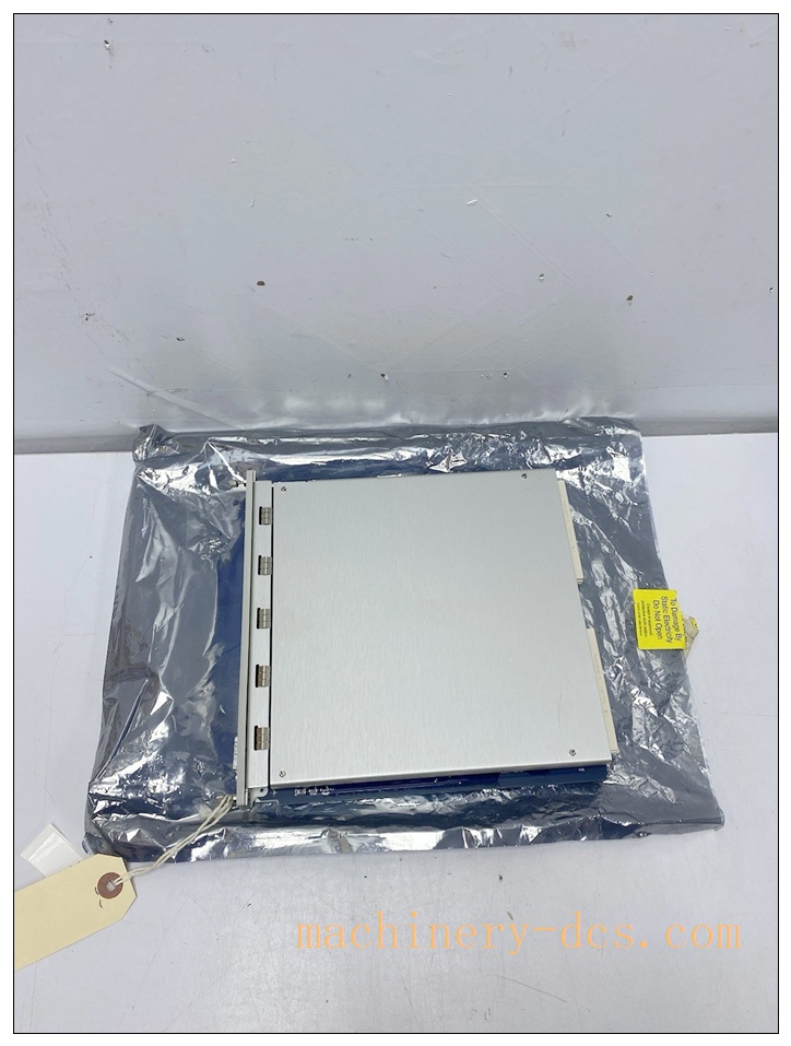
- Inspect module for transit damage. Confirm part number 136180‑01 and serial‑number match purchase order.
- Verify target 3500 rack is equipped with functional 3500/20 rack interface module, valid power supply and monitor modules.
- Prepare communication cables: CAT5e or higher Ethernet cable for RJ45 port; serial cable for rear RS‑232/422/485 terminal block.
- Clarify site communication requirements: IP address, Modbus protocol type, baud rate, target register list for DCS/SCADA integration.
Mechanical Installation
- Insert 136180‑01 into dedicated communication slot of 3500 rack, push firmly until backplane connector fully seats. Tighten front‑panel captive screws.
Hot‑swap allowed; rack power can remain active.
Electrical Wiring
- Connect Ethernet cable to front‑panel RJ‑45 port, link to local LAN switch.
- Wire serial‑communication signals to rear terminal block according to site drawing, observe RS‑485 bus termination requirements.
- Separate communication wiring from high‑power‑cable routes to reduce electromagnetic interference.
System Configuration & Commissioning
- Launch 3500 configuration software and connect to rack. Navigate to communication‑module setup page.
- Configure network parameters: set static IP address, subnet mask, gateway. Select active communication protocols (Modbus‑TCP / Modbus‑RTU).
- Configure Modbus register mapping: select measurement points, alarm flags and diagnostic parameters to be exported. Download configuration to rack non‑volatile memory.
- Verify front‑panel LED status: OK LED shall stay on; TX/RX LED blinks during data exchange.
- Conduct host‑system communication test: validate DCS/SCADA correctly receives real‑time values and alarm status. Trigger simulated alarms to confirm alarm‑flag transmission.
- Save full rack‑configuration backup file, place gateway into normal operation.

 Start Chat


 Send an Email


