
Description
Basler A404K Monochrome CMOS Area Scan Camera, A400k Series, Dual Camera Link, High‑Speed Industrial Vision Camera, Discontinued
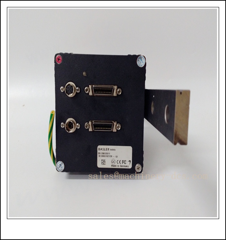
BASLER A404K
Technical Specifications
- Catalog Number: A404K
- Brand: Basler AG
- Product Type: Monochrome CMOS area scan industrial camera
- Resolution: 2352 × 1728 pixels
- Pixel Size: 7.4 μm × 7.4 μm
- Sensor Type: CMOS progressive scan
- Interface: Dual Camera Link (2 × 26 pin MDR)
- Data Output Modes: 4-tap 8 bit, 4-tap 10 bit, 8-tap 8 bit
- Max Data Rate: Up to 390.5 MB/s (8‑tap, 8‑bit)
- Exposure Control: Programmable exposure, step 4.56 μs; range 4.56 μs ~ 19.12 s
- Synchronization: Free-run, edge/level triggered external ExSync
- Flash Trigger: 4‑pin Hirose connector for strobe output
- Lens Mount: F‑mount
- Supply Voltage: 12 VDC ±10%, max 9.0 W
- Housing Dimension: 53.8 × 90 × 90 mm (without lens adapter); 85.3 × 90 × 90 mm with F‑mount adapter
- Weight: ~510 g (without adapter), ~615 g (with F‑mount adapter)
- Operating Temperature: 0 °C ~ +50 °C
- Features: AOI (Area of Interest), FPN/PRNU shading correction, programmable gain & offset
- Lifecycle Status: Discontinued; Last Time Buy: Aug 31, 2013; Last Service: Dec 31, 2016
- Certifications: CE, FCC
Key Features & Advantages
- Dual Camera Link high bandwidth interface: Delivers ultra‑high throughput for high‑resolution, high‑speed inspection systems.
- Large 2352 × 1728 monochrome CMOS sensor: Excellent sensitivity and low noise for precise feature detection and measurement.
- Multi‑tap readout flexibility: 4‑tap / 8‑tap modes allow users to balance frame rate and cable/frame grabber configuration.
- Built‑in AOI function: Read only selected region of sensor to boost frame rate for targeted inspection tasks.
- Onboard shading correction: FPN and PRNU correction reduces fixed pattern noise and improves image uniformity.
- Precision hardware trigger and strobe output: Tight synchronization with conveyors, motion systems and LED lighting.
- F‑mount lens interface: Compatible with large selection of high‑performance industrial lenses for macro and long working distance setups.
- Proven stable A400k platform: Designed for 24/7 continuous operation in machine vision production lines.
Application Fields
- Electronics PCB inspection, wafer and semiconductor component metrology
- Automotive component dimensional measurement and defect detection
- Print inspection, web inspection and label quality control
- High‑precision parts sorting and surface defect inspection
- Food & beverage packaging quality check
- Metrology and laboratory optical measurement systems
- Legacy high‑speed Camera Link vision retrofit projects
- Robotic guidance and positioning requiring high resolution monochrome imaging
Related Product Recommendations
- A404KC: Color version of A404K (same form factor and interface)
- A403K: Monochrome A400k single Camera Link variant
- A402K: Lower resolution monochrome A400k camera
- A405K: Higher speed A400k series CMOS camera
- acA2440‑20gm: Basler ace GigE monochrome replacement
- acA2440‑75um: Basler ace USB3 Vision upgrade model
- Basler Camera Link frame grabbers: suitable for CL dual tap acquisition
- F‑mount industrial fixed focal lenses
- High‑speed LED strobe controllers with trigger input
- A406K: High speed A400k series successor within the same family
Installation & Maintenance
Installation
- Mount the camera on rigid vibration‑damped bracket; avoid direct vibration from motors and actuators.
- Select matching F‑mount lens and adjust aperture / focus; protect sensor surface from dust and contamination.
- Use quality shielded Camera Link cables for dual tap connection; keep cable length within specification limits.
- Connect 12 VDC clean regulated power supply to the 6‑pin Hirose power connector; avoid ground loops.
- Wire ExSync trigger and flash strobe signal correctly for synchronized capture and lighting.
- Configure tap mode, bit depth, AOI, exposure and shading correction in frame grabber software.
- Separate Camera Link signal cables from high‑voltage AC, servo and VFD cables to reduce noise.
- Verify trigger polarity and strobe timing before running production inspection cycles.
Maintenance
- Perform periodic visual inspection of lens window, housing and connectors in scheduled downtime.
- Clean protective window only with lint‑free optical wipes and approved lens cleaner; do not touch CMOS sensor.
- Check cable integrity and connector locking; loose MDR connectors cause intermittent image corruption.
- Store original camera configuration parameters and shading correction files for restoration.
- Since this model is discontinued, maintain spare tested units for critical vision stations; repair support is limited.
- Diagnose image artifacts by checking shading correction, trigger jitter, power ripple and Camera Link signal integrity.
- Do not disassemble the camera housing; internal adjustment will void performance and damage sensor assembly.
- After replacement, re‑calibrate inspection recipes, pixel mapping and lighting timing before releasing to production.

 Send an Email