
Description
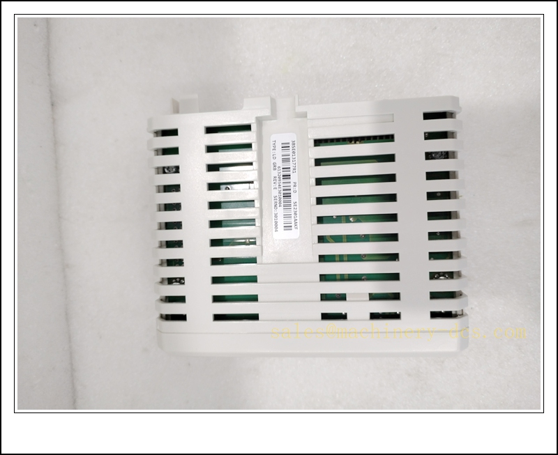
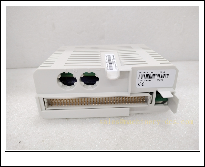
ABB LD GRB-01 Gray Encoder Adapter Board, Fiber Optic Encoder Interface Module for ACS6000 Medium Voltage Drives
Product Description
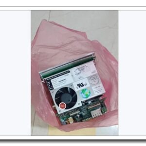
The 3AFE61320954P0001, designated LD GRB-01, is a dedicated encoder/fiber adapter electronic board engineered for ABB ACS6000 medium voltage drive systems. It acts as the signal bridge between the synchronous motor’s gray-code encoder terminal box and the AMC control board via fiber-optic channel 1. The module receives raw position and speed feedback from the motor-mounted encoder, converts electrical encoder signals into optical serial data, and transmits high-integrity feedback to the drive control unit for closed-loop speed and position regulation. Optical isolation eliminates ground loop interference and boosts noise immunity in high-power medium-voltage drive cabinets. On-board diagnostics monitor encoder power, signal integrity and fiber link status, reporting faults to the drive controller. This compact PCB board is widely used as a spare replacement for ACS6000 motor feedback loops.
Technical Specifications
- Brand: ABB
- Part Number: 3AFE61320954P0001
- Model: LD GRB-01
- Product Type: Gray Encoder Fiber Adapter Board
- Application Platform: ACS6000 Medium Voltage Drive
- Feedback Type: Gray-code encoder signal interface
- Communication Link: Fiber optic to AMC control board (Channel 1)
- Input Source: Synchronous motor encoder terminal box
- Power Supply: 24 VDC control power from drive rack
- Diagnostics: Encoder power loss, signal loss, fiber link break, board self-test
- Operating Temperature: 0 °C to +60 °C
- Storage Temperature: -20 °C to +70 °C
- Relative Humidity: 5% ~ 95%, non-condensing
- Mounting: PCB installation inside drive cubicle
- Approximate Weight: 0.21 kg
- Certification: CE, IEC industrial compliance
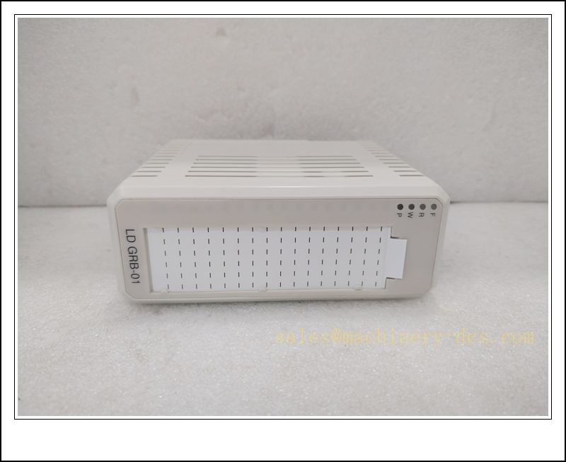
LDGRB-01 3BSE013177R1 3AFE61320954P0001
Application Scenarios
- ABB ACS6000 medium voltage synchronous motor drive position and speed feedback
- Large synchronous motors for mine hoists, heavy conveyor systems
- Oil & gas compressor and pump medium-voltage variable speed drives
- Power plant boiler fan and main feedwater pump high-power drives
- Marine propulsion synchronous motor ACS6000 control cabinets
- Cement and mining large gearless mill drive (GMD) feedback systems
- Paper industry high-speed large synchronous motor drives
- Spare part maintenance and retrofitting of existing drive units
8 Related ABB Model Recommendations
- 3AFE61320955P0001 – LD GRB-02 Encoder Adapter Board
- 3BHE009681R0001 – ABB AMC Control Board for
- 3BHE024541R0101 – ABB UFC718AE01 Interface Board
- 3AFE61340660P0001 – ABB Fiber Transmitter Board
- 3BHE014967R0001 – ABB RUSB-02 Interface Module
- 3AFE61310400P0001 – ABB Power Interface Board
- 3BHE005661R0001 – ABB Signal Conditioning Board
- 3AFE61331700P0001 – ABB Monitoring Board
Compatibility & Installation Pitfalls
Compatibility
- Exclusively designed for ABB medium voltage drive series; not compatible with ACS800, ACS880 low voltage drives.
- Must pair with the matching AMC main control board and gray-code encoder fitted to synchronous motors.
- Uses dedicated fiber channel 1 to AMC board; incorrect fiber port assignment triggers link loss alarms.
- Requires 24VDC control supply from the cubicle backplane; wrong supply voltage will damage the board.
- Encoder wiring pin assignment must match the motor terminal box drawing; mismatched pinout causes loss of position feedback.
- Drive firmware version must support LD GRB-01 encoder interface; outdated firmware cannot decode gray-code feedback.
Installation Pitfalls
- Isolate medium-voltage main power and 24V control supply before board replacement; residual voltage may damage components.
- Fiber optic connectors are fragile; avoid scratching the fiber end-face, and never bend fiber cables below minimum bend radius.
- Encoder signal cables are low-level sensitive wiring; route separately from high-power medium-voltage power cables to avoid EMI corruption.
- Confirm encoder type is gray-code; this board cannot work with incremental pulse encoders without hardware modification.
- Do not hot-swap the board while the drive is energized; live removal will interrupt motor feedback and cause drive trip.
- Check terminal screw torque during wiring; loose encoder terminals lead to intermittent speed fluctuation and random faults.
- Keep the PCB away from conductive dust, condensation and corrosive gas; contamination leads to short-circuit and signal drift.
- After replacement, verify encoder direction and position offset in drive parameters; reversed encoder phase results in unstable motor operation.
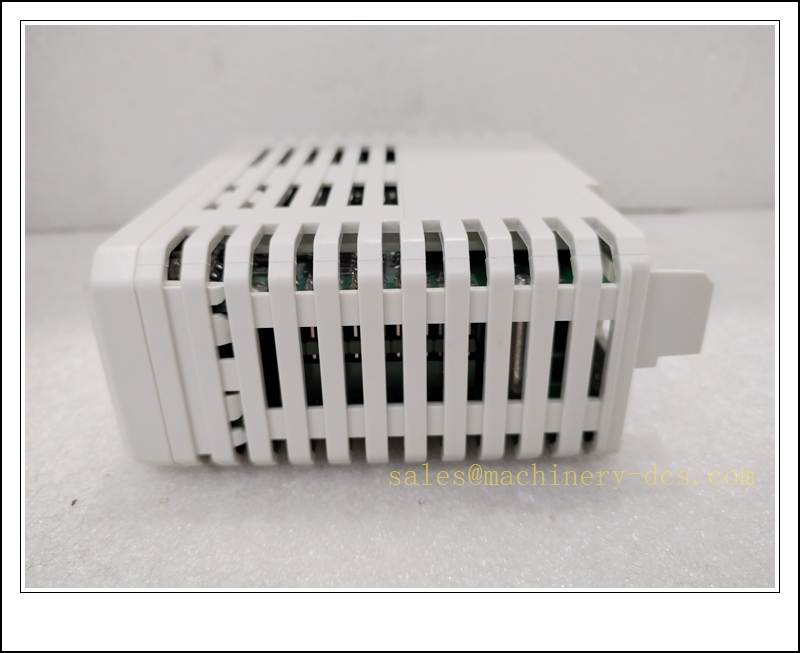
LDGRB-01 3BSE013177R1 3AFE61320954P0001
Standard Operating Procedure (SOP)
SOP for 3AFE61320954P0001 LD GRB-01 Encoder Adapter Board Inspection, Installation and Functional Test
- Pre-Installation Inspection Inspect the PCB for burnt traces, component damage, connector deformation or contamination. Confirm part number 3AFE61320954P0001. Verify compatibility with the drive, AMC control board and motor gray-code encoder. Review encoder wiring schematic and fiber layout. Apply lockout-tagout to medium voltage incoming power and 24V control supply.
- Cubicle Installation Mount the LD GRB-01 board into the designated slot inside the cubicle. Terminate encoder wiring from the motor terminal box to the board’s encoder connector. Connect the dedicated fiber optic cable between LD fiber channel 1 and the AMC board. Separate low-voltage encoder cables from high-power MV wiring and follow cubicle EMC grounding rules.
- Drive Parameter Configuration Restore 24V control power with main MV power disconnected. Access the control panel, select the correct encoder type (gray-code), verify encoder resolution and rotation direction parameters. Save parameter set to drive memory and external backup. Resolve fiber link or encoder communication alarms before enabling high voltage.
- Feedback Signal Test Run the drive in no-load low-speed mode. Monitor encoder raw position and speed values on the AMC board diagnostic menu. Simulate loose encoder wiring and fiber disconnection to validate fault alarm reporting. Confirm stable position reading without jump or drift. Record signal quality and alarm response in the maintenance log.
- Load Commissioning Close the medium voltage breaker and perform controlled motor ramp-up test. Monitor speed regulation stability under varying load conditions. Confirm closed-loop control responds correctly to speed reference changes, and encoder faults trigger safe drive shutdown instead of uncontrolled overspeed.
- Return to Service Reset fault latches and acknowledge diagnostic alarms. Remove lockout-tagout. Continuously monitor encoder signal quality, fiber link status and board LED indicators through the observation window. Notify operation personnel that the encoder adapter board is commissioned and ready for production.
- Periodic Maintenance and Replacement During scheduled shutdown, inspect fiber connector cleanliness, encoder terminal tightness and PCB dust accumulation. Perform encoder signal proof-test according to drive maintenance schedule. If persistent fiber or encoder signal faults cannot be cleared, execute full power isolation before board replacement. After replacement, recheck encoder phasing, position offset and full speed loop test before releasing the drive online.

 Start Chat


 Send an Email


