
Description
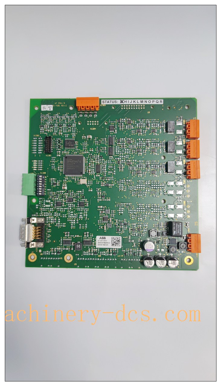
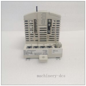
ABB CVM12B 3BHE037864R1110 is a high-precision Current & Voltage Measurement Board
Product Title & Description
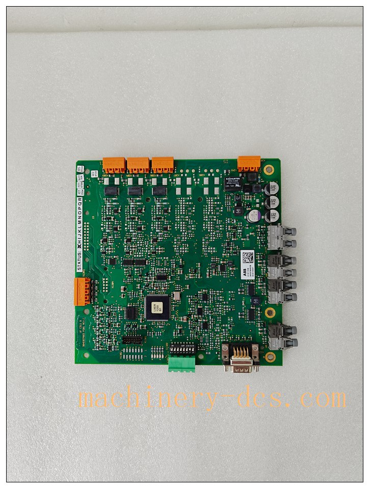
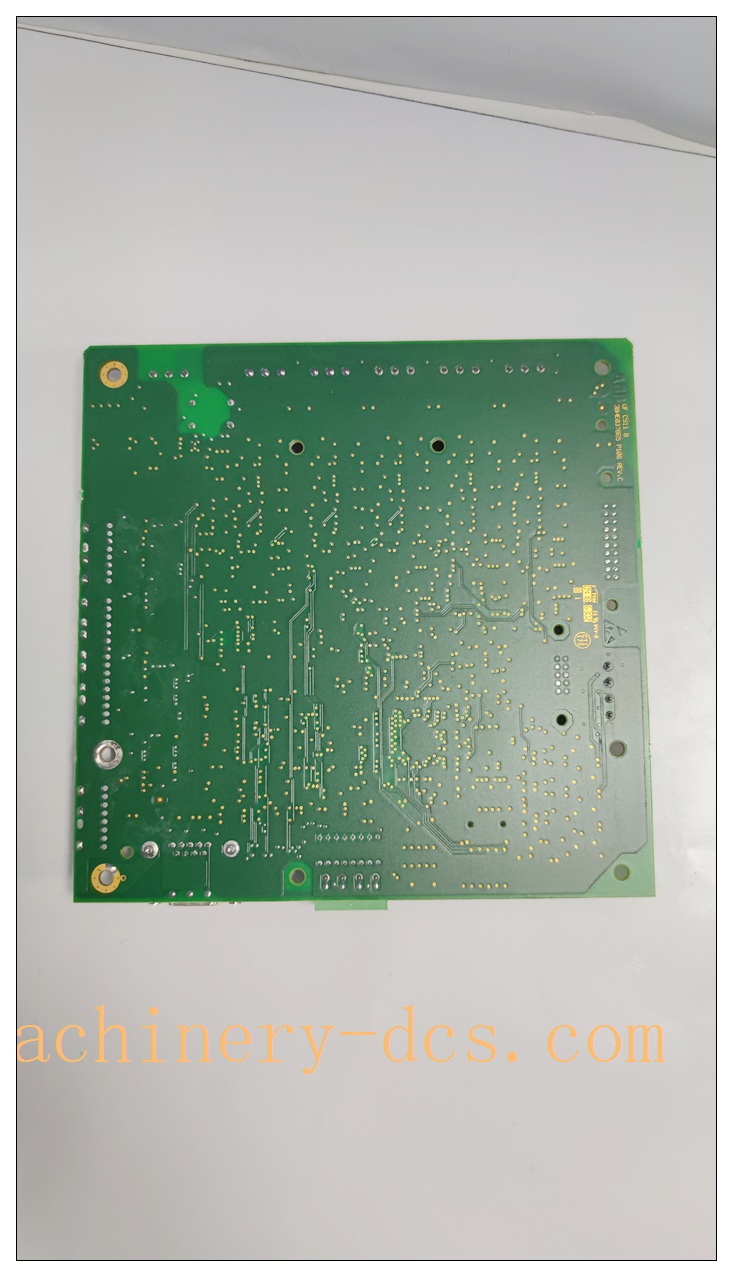
Model: 3BHE037864R1110 (CVM12B / CVMI2B, UFC911B110) The ABB CVM12B 3BHE037864R1110 is a high-precision Current & Voltage Measurement Board for ABB ACS1000 medium voltage IGCT variable frequency drives. It samples the drive’s AC output voltage and current signals, converts analog measurements to digital optical signals and transmits them to the main drive controller for closed-loop vector control and drive protection. Widely applied in power plants, mining, oil & gas, metallurgy large fans, pumps and compressor MV drive systems, it provides critical electrical feedback for high-power IGCT medium voltage drives.
Core Product Overview
CVM12B is the signal measurement feedback board inside ABB ACS1000 medium voltage drive cabinet. It collects 3-phase output current and voltage signals from the power stage, performs high-speed sampling and isolation conversion, then sends digitized measurement data via fiber optics to the main drive control unit. It delivers real-time high accuracy voltage/current feedback for vector control algorithm execution. It also detects overcurrent, phase imbalance, overvoltage and undervoltage conditions, and sends fault alarm signals to the main controller for rapid drive protection shutdown. Optical communication achieves full galvanic isolation between high voltage power circuit and low-voltage control electronics, effectively suppressing EMI interference in high-power drive cabinets. It is a critical spare part for maintenance and retrofit of legacy ABB ACS1000 MV drives.
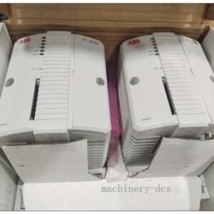
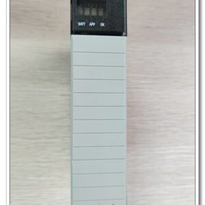
3BHE037864R1110 CVM12B UFC911B
Main Technical Specifications
- Manufacturer: ABB
- Part Number: 3BHE037864R1110
- Alias: CVM12B / CVMI2B, UFC911B110
- Product Type: Voltage & Current Measurement Interface Board
- Compatible Drives: ABB ACS1000 medium voltage IGCT drives
- Measured Signals: 3-phase output voltage, 3-phase output current
- Communication Interface: Fiber optic links to drive main controller
- Auxiliary Supply: 24 VDC control power
- Mounting: Rack mount inside ACS1000 MV drive cabinet
- Operating Temperature: -20°C ~ +60°C
- Storage Temperature: -40°C ~ +85°C
- Relative Humidity: 5% ~95%, non-condensing
- Protection Class: IP20 (installed inside drive cabinet)
- Cooling: Forced air cabinet cooling
- Certifications: CE, UL
- Function: High-speed sampling, signal isolation, fault detection, optical data transmission
Quality Control Procedures
ABB medium voltage drive electronic boards comply with ISO9001 and IEC adjustable speed drive standards.
- Incoming Component Inspection: High precision sampling chips, optical transceivers, isolation transformers and PCBs are screened from qualified suppliers.
- Automated Assembly & Serial Traceability: SMT soldering and assembly. Unique serial number for full lifecycle traceability.
- Full Functional Calibration & Test: Each board undergoes signal sampling calibration, optical transmit/receive test, over-limit fault simulation and isolation test.
- Environmental Stress Screening: Batch samples perform thermal cycling, vibration and EMC testing for high-power drive cabinet environments.
- Final Inspection & Packing: Visual inspection, anti-static and shockproof export packaging, factory test documentation included.
3BHE037864R1110 CVM12B UFC911B
Brand Related Model Recommendations
- 3BHE037864R0101 UFC911B101: Earlier revision CVM12B measurement board for ACS1000.
- 3BHE037864R1106 UFC911B106: Alternative revision variant.
- 3BHB004661R0101 KUC711AE101: GUSP gate power supply board, paired together in cabinet.
- 3BHB003431R0001: IGCT gate unit board, the power semiconductor gate driver in .
Frequently Asked Questions (FAQ)
Q1: What drive system is 3BHE037864R1110 used for? A1: It is exclusively for ABB medium voltage IGCT variable frequency drives.
Q2: What is the core function of ? A2: It measures the drive’s 3-phase output voltage and current, converts analog signals into optical digital feedback for the drive controller to run vector control and protection logic.
Q3: Is it hot-swappable? A3: No. Before removing or replacing this board, all medium voltage and auxiliary 24V power must be fully locked out and isolated; high voltage hazard exists inside the cabinet.
Q4: Why use fiber optical communication? A4: Fiber provides complete galvanic isolation, preventing high voltage noise and surge from damaging low-voltage control electronics.
Q5: What is the warranty for original ABB 3BHE037864R1110 ? A5: Original ABB board carries standard 12-month factory warranty against manufacturing defects under proper installation and operating conditions.
Installation & Configuration Guide
7.1 Pre-installation Preparation
Verify part number 3BHE037864R1110 . Inspect PCB, terminals and fiber ports for scratches or damage. Prepare drive cabinet drawings, optical fiber cables, 24VDC control power supply and ABB commissioning tool. Lock out & tag all medium voltage and auxiliary power before entering the MV drive cabinet. Wear ESD protection.
7.2 Installation Steps
Insert board into its designated rack slot inside cabinet and secure mounting screws. Connect 24VDC auxiliary control power terminals. Install optical fiber links between and main drive controller; keep fiber connectors clean and avoid sharp bending. Connect voltage/current transducer signal wiring. Tighten all signal and power terminals, verify protective earthing. Maintain cabinet airflow for forced cooling.
7.3 System Configuration & Commissioning
Power up only the 24V control supply (medium voltage remains disconnected). Check board LED status and optical communication link. Use ABB drive commissioning software to read voltage and current measurement values, verify sampling accuracy. Simulate overcurrent/overvoltage signals to test drive protection response. After successful low voltage test, perform step-by-step medium voltage energization, monitor real-time feedback signals. Save commissioning parameters and baseline logs.
7.4 Maintenance & Precautions
During plant shutdown outages, inspect fiber connector cleanliness, terminal tightness, PCB dust accumulation and cabinet cooling fan status. Do not open the PCB housing. High voltage danger in drive cabinet. If measurement deviation or communication fault appears, check transducers, fiber links and 24V control supply before replacing .

 Start Chat


 Send an Email


