
Description
Product Core Introduction
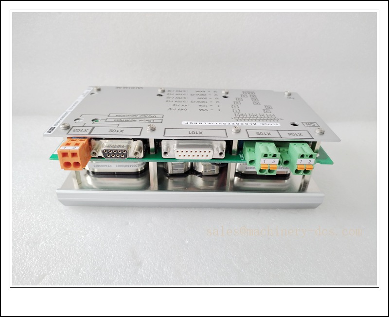
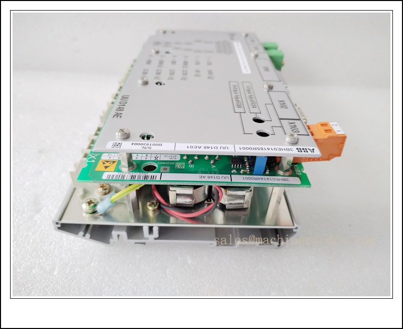
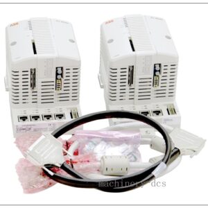
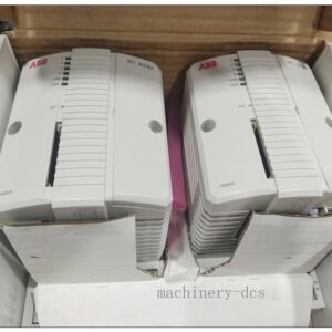
The ABB 3BHE014185R0001 UUD148AE01 is a high-performance excitation control interface module belonging to ABB’s UNITROL® family of automatic voltage regulators (AVR) and static excitation systems. Designed and manufactured at ABB’s power generation facilities in Switzerland, it functions as a critical signal interface and control processing unit that manages field excitation current regulation, generator terminal voltage control, and reactive power compensation for synchronous generators. It serves as an essential spare part for UNITROL 1000, UNITROL 5000, and UNITROL 6000 excitation system platforms, enabling reliable lifecycle extension for thermal, hydro, and gas turbine power generation assets worldwide.
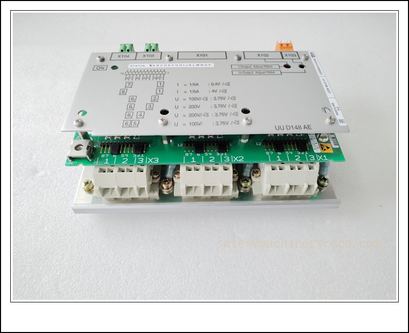
3BHE014185R0001 UUD148AE01
Key Technical Specifications
| Parameter | Details |
|---|---|
| Official Part Number | 3BHE014185R0001 |
| Model Designation | UUD148AE01 |
| Product Family | ABB UNITROL® Excitation Control System |
| Core Function | Excitation current regulation, terminal voltage control, and reactive power management |
| Nominal Supply Voltage | 24 V DC control power input, with internal galvanic isolation for signal channels |
| Input Signal Types | Analog 4-20 mA / 0-10 V DC, plus digital status and trip contact inputs |
| Output Signal Types | Isolated analog setpoint outputs and relay contact outputs for thyristor firing control |
| Communication Interfaces | Native support for ABB proprietary UNITROL communication bus and standard fieldbus gateways |
| Measurement Accuracy | ±0.1% full-scale precision for voltage and current feedback channels |
| Environmental Rating | Certified for industrial power plant control room conditions, with conformal-coated PCB for dust and humidity resistance |
| Country of Origin | Switzerland |
| Protection Rating | IP20 for cabinet-mounted installation |
| Functional Safety | Integrated watchdog and self-diagnostic functions compliant with power generation safety requirements |
Recommended Models from the Same Series
For users exploring compatible alternatives or extended functionality within ABB’s excitation control portfolio:
- UUD148AE02: Direct successor variant with enhanced firmware and expanded communication protocol support, fully backward compatible with the UUD148AE01 footprint
- 3BHE014185R0002: Higher-precision revision of the same interface module, optimized for large-capacity turbo-generator excitation systems
- UNITROL 1020 AVR Controller: Compact automatic voltage regulator for small hydro and diesel generator applications, integrating core excitation control functions in a single standalone unit
- UNITROL 6800 Static Excitation System: Full-featured high-power static excitation platform, natively integrating this interface module for comprehensive generator control and protection
Safety Precautions Before Installation
- High-Voltage Hazard: Never work on the excitation system while the generator is energized or the field circuit is live. Always follow the plant’s lock-out/tag-out (LOTO) procedures and ensure the field breaker is fully open before commencing work.
- Electrostatic Discharge Protection: Wear a properly grounded anti-static wrist strap and use ESD-safe packaging when handling this module. Static discharge can permanently damage sensitive control electronics.
- Verify System Isolation: Confirm that all control and power supplies are fully isolated and discharge stored energy in capacitors before removing or inserting the module.
- Personnel Qualification: Installation and configuration must be performed by qualified personnel with specific training on ABB UNITROL excitation systems and high-voltage power generation equipment.
- Documentation Review: Read the official ABB UNITROL system manual and this module’s specific wiring diagram before starting any installation procedure.
Hardware Installation Steps
- Pre-Installation Inspection: Unpack the module and inspect for any physical damage during transit. Verify that the model number 3BHE014185R0001 UUD148AE01 matches your system’s spare parts specification.
- Power Down and Isolate: Complete LOTO procedures, open the generator field breaker, and isolate all control power supplies feeding the excitation cabinet.
- Remove the Existing Module: Disconnect all field wiring, clearly labeling each cable and its termination point. Release the mounting fasteners and carefully slide the old module out of its designated rack slot.
- Insert the New Module: Align the new module with the guide rails of the rack slot, insert it smoothly until the backplane connector fully engages, and secure all front-panel fasteners to the specified torque.
- Restore Wiring: Reconnect all labeled cables according to the wiring diagram, ensuring proper termination torque and correct polarity for all signal and power connections.
- Basic Visual Inspection: Confirm that all connections are secure, no foreign objects are present inside the module, and all status indication LEDs are visible for the subsequent power-up test.
System Configuration Procedure
- Power-Up Sequence: Restore the control power supply following the plant’s standard energization procedure, and observe the module’s initial self-diagnostic LED indication.
- Communication Establishment: Connect the engineering workstation to the excitation control system via the appropriate communication interface, and confirm the module is correctly recognized by the control processor.
- Parameter Verification: Load the existing parameter set from the system backup, and verify all excitation control parameters including voltage setpoint, PID gains, limit settings, and protection thresholds are correctly applied.
- Calibration Check: Verify the accuracy of all analog feedback channels (terminal voltage, field current, field voltage) by comparing the module readings against reference instruments.
- Firmware Compatibility Confirmation: Ensure the module firmware version is compatible with the existing system controller firmware, and upgrade if required per ABB’s official recommendation.
- Save Configuration: Once all parameters are verified and correct, save the complete configuration to non-volatile memory and create a backup copy for future reference.
Post-Installation Verification Points
- Self-Diagnostic Check: Confirm all status LEDs indicate normal operation with no fault or alarm indications from the module’s internal self-diagnostics.
- Communication Link Test: Verify stable communication between the module and the system controller, with no data transmission errors or interruptions.
- Analog Signal Accuracy: Compare all measured values against calibrated reference instruments to confirm measurement accuracy remains within the specified ±0.1% tolerance.
- Functional Test at Reduced Excitation: Perform a controlled low-level excitation test to verify the module correctly regulates field current in response to setpoint changes.
- Protection Function Verification: Simulate overvoltage, overcurrent, and loss-of-field conditions to confirm the module’s protection functions correctly operate and trip the excitation system.
- Load Test Under Operating Conditions: Gradually increase generator load and verify stable voltage regulation and reactive power control throughout the full operating range.
- Documentation Update: Record the replacement in the plant maintenance log, including the new module’s serial number and the date of installation.
Application Scenarios & Key Features
- Application Scenarios:
- Thermal power plants: Excitation control for coal, gas, and oil-fired turbine generators maintaining stable terminal voltage and reactive power output
- Hydroelectric stations: Precise excitation regulation for hydro-generators ensuring grid-compliant voltage and frequency stability
- Nuclear power facilities: Safety-related generator excitation control with full redundancy and fault-tolerant architecture
- Industrial power generation: Captive power plant generator excitation for refineries, steel mills, cement plants, and desalination facilities
- Key Features:
- Full backward compatibility with all legacy ABB UNITROL excitation system architectures, enabling direct drop-in replacement without modifying existing cabinet wiring
- Precision ±0.1% measurement accuracy for all critical feedback channels, ensuring stable generator terminal voltage under all load conditions
- Integrated self-diagnostic and watchdog functions, enabling early detection of potential failures before they impact generator availability
- Compact modular design with conformal coating, providing reliable operation in the dust and humidity conditions typical of power plant control rooms
Frequently Asked Questions (FAQs)
Q1: Can the UUD148AE01 directly replace older excitation interface modules in my UNITROL system?
A: Yes, it maintains full pin-to-pin and software compatibility with legacy UNITROL excitation system interface modules, requiring only standard parameter verification after installation.
Q2: What documentation do I need to complete the installation?
A: You will need the official ABB UNITROL system manual, the specific wiring diagram for your excitation cabinet configuration, and the approved plant switching procedure for generator isolation.
Q3: How do I verify the module is functioning correctly after installation?
A: Follow the post-installation verification points, including LED status check, communication test, analog accuracy verification, and controlled functional testing at reduced excitation levels.
Q4: What is the recommended spare parts strategy for this module?
A: ABB recommends maintaining at least one spare module in the plant spare parts inventory for critical generators to minimize downtime in the event of a module failure.

 Send an Email