
Description
ABB 3BHB007440P0001 Gate Drive Interface Board for IGCT Power Modules
Product Description
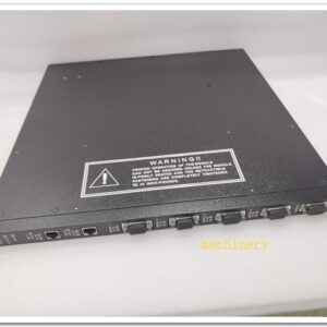
The 3BHB007440P0001 is an ABB gate drive interface PCB designed for IGCT (Integrated Gate Commutated Thyristor) power stacks used in high-power medium voltage converters. It acts as the isolated signal intermediary between the main control board and the IGCT gate units. The board receives optical trigger commands from the control system, converts optical signals into drive enable and gate pulse signals for IGCTs, and feeds back device status, fault messages and snubber circuit diagnostics via fiber links to the master controller. Galvanic isolation through optical communication protects low-voltage control electronics from high-potential power circuit noise and transients. It is commonly deployed as a critical spare for ABB medium voltage variable speed drives and power conversion systems.
Technical Specifications
- Brand: ABB
- Part Number: 3BHB007440P0001
- Product Type: IGCT Gate Drive Interface Board
- Controlled Device: IGCT power semiconductor
- Communication: Fiber-optic transmit / receive channels for gate commands and status feedback
- Control Supply: 24 VDC auxiliary power from converter cubicle
- Diagnostic Functions: Gate signal loss, IGCT fault detection, snubber failure, board self-test
- Operating Temperature: 0 °C to +60 °C
- Storage Temperature: -20 °C to +70 °C
- Relative Humidity: 5% ~ 95 %, non-condensing
- Mounting: PCB assembly inside medium voltage power cabinet
- Weight: Approx. 0.24 kg
- Compliance: CE, IEC industrial power electronics standards
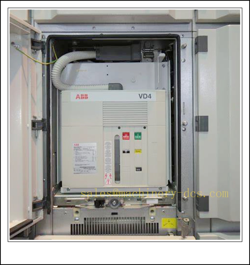
3BHB007440P0001
Application Scenarios
- ABB medium voltage converters based on IGCT power technology
- Large synchronous and induction motor drives for mining conveyors
- Oil and gas high-power compressor and pump variable speed systems
- Power plant boiler fans, induced draft fans and feedwater pump drives
- Gearless mill drives in mineral processing and cement plants
- Marine high-power propulsion converters
- Static frequency converters and grid-tied power quality equipment
- Maintenance spare replacement for existing ABB IGCT converter racks
8 Related ABB Model Recommendations
- 3BHB003416R0101 – ABB IGCT Gate Unit
- 3BHE009681R0001 – ABB AMC Main Control Board
- 3BHB005241R0001 – Snubber Monitoring Board
- 3AFE61320954P0001 – LD GRB-01 Encoder Adapter Board
- 3BHE024541R0101 – UFC718AE01 Interface Board
- 3BHB010334R0001 – Fiber Transmitter Board
- 3BHE014967R0001 – RUSB-02 Signal Interface Module
- 3BHB006348R0001 – Power Voltage Sensing Board
Compatibility & Installation Pitfalls
Compatibility
- Designed for ABB IGCT medium voltage converter platforms; not compatible with IGBT-based ACS800 / ACS880 low voltage drives.
- Must be matched with corresponding ABB IGCT gate units and master AMC control boards.
- Fiber channel allocation must follow the converter schematic; mismatched fiber ports cause missing gate pulses and converter trips.
- Requires clean, regulated 24 VDC cubicle auxiliary supply; overvoltage will destroy the opto-receiver components.
- The board firmware is factory-configured for specific IGCT types; it cannot be repurposed for other semiconductor families.
- The overall power stack layout, snubber circuit parameters and control software version must align with this board’s design revision.
Installation Pitfalls
- Perform full lockout-tagout of medium voltage and 24 V auxiliary power before service; high DC link voltage remains in capacitors long after shutdown.
- Treat fiber connectors carefully; scratches on fiber end-faces or bending beyond minimum radius degrade optical signal and trigger intermittent gate faults.
- Keep low-energy fiber and control wiring separated from high-current power busbars to avoid electromagnetic interference.
- Never hot-swap the board while the converter is energized; loss of gate commands can lead to uncontrolled semiconductor failure and short-circuit.
- Verify the board revision matches the original unit; different hardware revisions are not always drop-in compatible without parameter and software updates.
- Check all terminal and connector locking mechanisms; loose contacts produce random gate misfire faults that are difficult to reproduce.
- Protect the PCB from conductive dust, moisture and corrosive ambient air; contamination may cause surface tracking under high-voltage conditions.
- After replacement, test each fiber channel individually; reversed transmit/receive fibers result in no gate drive feedback and immediate converter blocking.
Standard Operating Procedure (SOP)
SOP for 3BHB007440P0001 Gate Drive Interface Board Inspection, Installation and Functional Test
- Pre-Installation Inspection Examine the PCB for burnt components, trace damage, cracked connectors or surface contamination. Confirm the part number 3BHB007440P0001. Cross-check hardware revision against the original drawing, IGCT gate unit type and converter control software version. Review fiber assignment diagrams and lockout-tagout all medium voltage and 24 V auxiliary circuits.
- Cubicle Installation Mount the gate drive interface board in its designated slot within the power converter cubicle. Secure all connectors. Route optical fibers according to the channel assignment table between the AMC control board, this interface board and IGCT gate units. Segregate fiber and signal cables from high-voltage busbars and apply EMC grounding as specified in ABB documentation.
- Control Configuration Restore 24 V auxiliary power with medium voltage locked out. Access the converter control interface, verify semiconductor type, pulse timing and fault masking parameters. Save the parameter set to local memory and external backup. Clear existing fiber and gate drive related faults before proceeding to signal testing.
- Fiber and Gate Pulse Test Execute the converter’s low-potential signal test mode. Check optical signal transmission and reception for every assigned fiber channel. Monitor gate command pulses and fault feedback status from each IGCT unit. Simulate fiber disconnection to confirm proper fault reporting and safe blocking. Record signal integrity results in the maintenance log.
- High-Voltage Commissioning Release the medium voltage interlock only after all signal tests pass. Energize the converter step by step, starting with no-load excitation. Ramp the motor speed reference slowly and observe IGCT status, snubber monitoring and gate feedback signals. Confirm that any detected gate or device fault triggers immediate safe blocking rather than uncontrolled conduction.
- Return to Service Reset all fault latches and acknowledge diagnostic alarms. Remove lockout-tagout. Keep the converter under supervised operation and continuously monitor board LED status, fiber quality and IGCT feedback for the observation period. Notify operating staff that the gate drive interface board is commissioned and ready.
- Periodic Maintenance and Replacement During scheduled outages, inspect fiber end-face cleanliness, connector tightness and PCB dust accumulation. Run the converter’s built-in gate drive proof-test routine. If persistent optical communication or gate interface faults cannot be resolved, isolate all power sources before replacement. After fitting the spare board, repeat fiber mapping, pulse verification and full no-load / loaded commissioning test before returning the equipment online.

 Start Chat


 Send an Email


