
Description
3500/25 SIL2-01-03-00 Bently Nevada SIL2 Certified Dual-Channel Keyphasor Module with Internal IS Barrier & Internal Termination
Product Overview & Detailed Description
The 3500/25 SIL2-01-03-00 is a safety-certified enhanced Keyphasor (speed and phase reference) module designed for the Bently Nevada 3500 machinery protection system. As a critical timing and synchronous reference unit, this module provides precise rotational speed, phase angle, and once-per-revolution (1X) trigger signals for all vibration, position, and dynamic vector measurements across the entire rack. The model coding defines core configurations: 01 stands for standard half-height dual-channel layout; 03 represents internal intrinsic safety barrier design with internal field wiring termination; 00 indicates standard factory calibration without custom agency modifications, and the SIL2 rating confirms compliance with IEC 61508 functional safety standards for safety instrumented system (SIS) deployment.
Equipped with built-in IS barriers, this module eliminates the need for external safety barrier terminals, allowing direct connection of Keyphasor proximity probes and magnetic pickups in Zone 2 / Division 2 hazardous areas. It supports two independent input channels for redundant speed/phase acquisition and delivers high-stability synchronous reference signals to vibration monitors, transient data interfaces, and relay output modules. Accurate phase and speed tracking enables precise fault diagnosis including rotor imbalance, misalignment, bearing wear, and rotational surge. With on-board self-diagnosis and SIL2 fault-tolerant capability, it guarantees high availability and reliable trip logic for turbine, compressor, and rotating machinery safety protection.
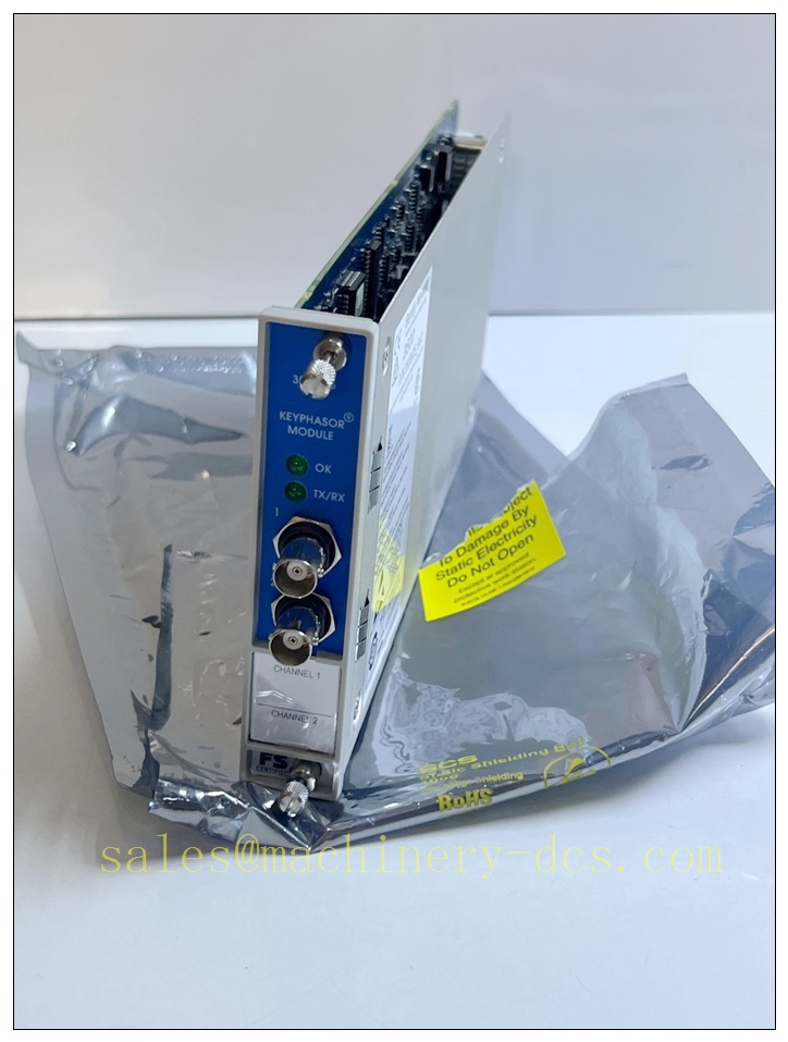
3500/25 SIL2-01-03-00
Core Technical Parameters
3.1 Functional & Signal Parameters
- Channel Configuration: 2 independent Keyphasor input channels
- Supported Transducers: 3300 XL proximity probes, passive magnetic pickups
- Input Signal Range (IS Barrier Type): +5 V to -11 V
- Minimum Detectable Speed: 200 RPM (magnetic pickup application)
- Maximum Input Frequency: 20 kHz high-speed pulse response
- Phase Accuracy: High-precision angle synchronization for 1X/2X vector calculation
- Input Impedance: 21.8 kΩ minimum
- Buffered Output: Isolated pulse output for external data acquisition and waveform capture
3.2 Electrical & Safety Ratings
- Safety Integrity Level: certified per IEC 61508
- Power Consumption: 3.2 W typical operating power
- IS Barrier Specification: Built-in certified intrinsic safety circuit for hazardous area direct wiring
- Termination Mode: Internal termination (no external terminal block required)
- Self-Diagnosis: Continuous probe fault detection, signal loss, short/open circuit diagnosis
3.3 Environmental & Physical Parameters
- Operating Temperature: -20 °C to +65 °C (-4 °F to +149 °F)
- Storage Temperature: -40 °C to +85 °C (-40 °F to +185 °F)
- Relative Humidity: 0%–95% non-condensing
- Mechanical Standard: Standard 3500 half-height hot-swappable module
- Dimension: 241.3 mm × 24.4 mm × 103.1 mm
- Weight: 0.40 kg (0.88 lb)
- Compliance: API 670, CE EMC/LVD, IEC 61508
Compatibility & Installation Pitfalls
4.1 System & Hardware Compatibility
This module is fully compatible with standard 3500/05 14-slot system racks and all 3500 series monitoring and safety modules. It perfectly matches 3500/40 proximity monitors, 3500/42 vibration monitors, 3500/50 temperature monitors, 3500/33 relay output modules, and 3500/92 communication gateway modules. It supports system configuration via 3500 Rack Configuration Software V2.3 and above. The built-in IS barrier version is compatible with hazardous-area SIL system configurations and can work with 3500/04 IS earthing modules for certified explosive zone deployment. It supports up to two 3500/25 modules per rack for four Keyphasor signal inputs.
4.2 Critical Installation Pitfalls & Common Risks
- Internal Termination Misoperation: This 03-config module adopts internal termination design. External terminal resistors or parallel termination accessories are prohibited; extra external termination will cause signal attenuation and phase drift, invalidating measurement accuracy.
- Low-Speed Signal Loss Risk: Magnetic pickup applications below 200 RPM cannot generate valid trigger pulses, resulting in lost Keyphasor signals. For low-speed rotating equipment, proximity-type Keyphasor probes are mandatory.
- Hazardous Area Wiring Violation: Although the module integrates IS barriers, field cables must maintain 50 mm isolation from non-IS high-current cables. Mixed routing will degrade barrier performance and violate zone certification requirements.
- SIL Configuration Tampering Risk: Arbitrary modification of Keyphasor threshold, hysteresis and filter parameters may disable safety integrity. All safety-related parameters must follow factory-approved range limits.
- Improper Slot Arrangement: Keyphasor timing signals are system synchronous reference sources. Installing this module far from vibration monitor modules may introduce tiny synchronous delay, affecting vector amplitude and phase consistency. Centralized slot layout is recommended.
- Hot-Swap Safety Limitation: Non-safety channel hot swap is allowed, but trip-associated Keyphasor channels require LOTO power-off operation during replacement to avoid temporary reference signal loss and false system trips.
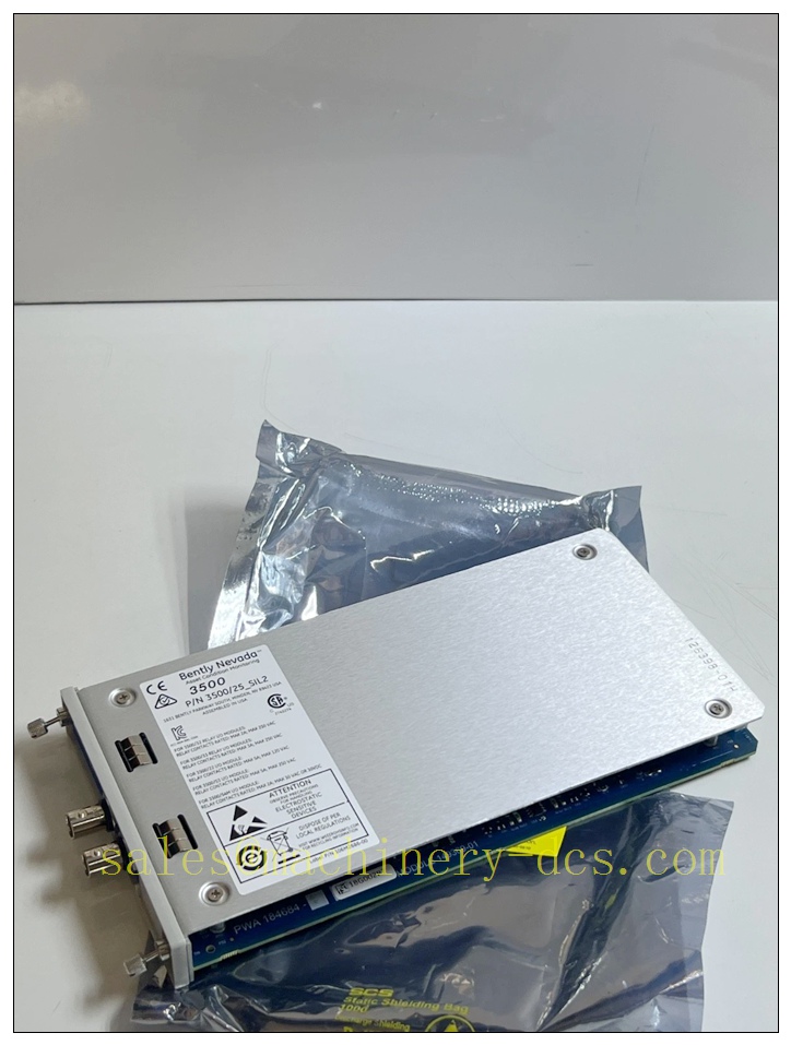
3500/25 SIL2-01-03-00
Standard Operating Procedure (SOP)
5.1 Pre-Installation Inspection
Verify model correctness (3500/25 -01-03-00) with internal barrier and internal termination; inspect module circuit, terminals and LED indicators for integrity; confirm compatibility of probe type and speed range; check hazardous area cable compliance and grounding system separation (IS earth vs protective earth); prepare configuration software and backup files.
5.2 Standard Installation & Commissioning Steps
1. Execute LOTO safety procedure for rack installation; 2. Insert the 3500/25 module into a valid non-power slot and fully lock the front handle; 3. Route field Keyphasor probe cables strictly separated from power and relay wiring; 4. Complete internal termination wiring without additional external resistors; 5. Power on the rack and confirm module online status via configuration software; 6. Set speed threshold, pulse edge trigger, and filter parameters according to machinery characteristics; 7. Perform shaft jogging and full-speed rotation test to verify stable pulse capture and phase synchronization; 8. Cross-check vibration vector 1X amplitude and phase data to confirm synchronous accuracy; 9. Save and archive the final SIL-compliant configuration file.
5.3 Daily Operation & Maintenance
Monitor real-time Keyphasor signal status, speed value and synchronous health through system host; quarterly check cable tightness, shielding integrity and wiring isolation distance; semi-annually perform speed simulation test and phase accuracy verification; annually calibrate system synchronous reference and confirm functional integrity; clean module ventilation area to prevent overheating-induced signal jitter.
5.4 Module Replacement Procedure
Disable relevant safety trip logic and implement LOTO isolation; disconnect field probe wiring with clear marking; remove the old module and install a new qualified unit; restore wiring strictly following original channel definition; reapply calibrated configuration parameters; perform full speed and phase synchronization test; validate linkage with vibration and trip modules; restore system safety function after full verification.
Application Scenarios
The 3500/25 -01-00-03 module is deployed in safety-critical rotating machinery systems requiring -certified speed and phase synchronous monitoring, including: thermal power steam turbine and generator sets, petrochemical large centrifugal compressors and turbo machinery, oil & gas onshore/offshore platform rotating equipment, metallurgical high-speed fans and rolling mills, chemical hazardous zone compressor units, and reciprocating machinery P-V curve analysis systems. It serves as the core timing reference for machinery vector vibration analysis, fault diagnosis, and safety trip interlock.
Supporting Components
- System Rack: 3500/05 14-slot standard industrial rack chassis
- Power Unit: 3500/15 AC/DC redundant power supply module
- Hazardous Area Matching: 3500/04-01 IS Earthing Module
- Transducer Devices: 3300 XL 8mm Proximity Keyphasor Probe, Magnetic Pickup Sensor
- Data Interface: 3500/22M TDI Transient Data Interface Module
- Configuration Tool: 3500 Rack Configuration Software V2.3+
- Field Accessories: Shielded coaxial probe cable, anti-interference signal wire, isolation bracket
Brand Matching Model Recommendations (8 Models)
All listed models are original Bently Nevada 3500 series modules, fully compatible with rack bus, firmware, and safety architecture for integrated system construction:
- 3500/15-01-00-00: AC Redundant Power Supply Module, provides stable bus power for synchronous measurement system
- 3500/92-02-01-00: System Communication Gateway Module, uploads speed and phase synchronous data to upper systems
- 3500/22M-01-02-00: TDI Transient Data Interface, captures high-speed dynamic vibration and Keyphasor waveforms
- 3500/40 SIL-01-00: Proximity Monitor Module, matches synchronous shaft position monitoring
- 3500/42-01-00-00: Multi-Channel Vibration Monitor Module, relies on Keyphasor signal for vector analysis
- 3500/50-01-00-00: Temperature Monitor Module, realizes multi-parameter synchronous condition monitoring
- 3500/33 -01-00: 16-Channel Relay Module, executes speed-abnormal safety trip output
- 3500/04-01-00: IS Earthing Module, ensures intrinsic safety integrity for barrier-type Keyphasor system

 Start Chat


 Send an Email


