
Description
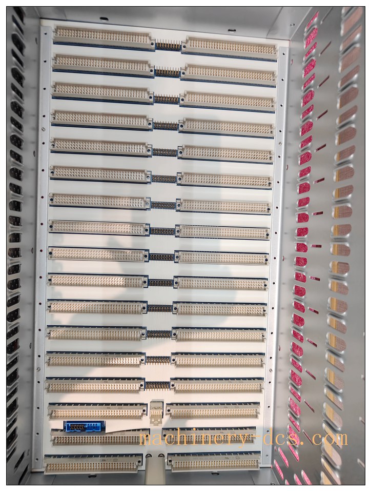
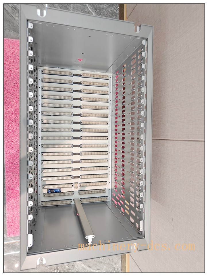
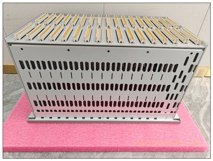
3500/05-01-02-00-00-01 Bently Nevada 19-inch EIA Rack-Mount System Rack, 14-Slot Full-Size Chassis with CE Compliance
Product Overview & Detailed Description
The 3500/05 system rack serves as the mechanical and electrical backbone of the entire Bently Nevada 3500 machinery protection platform. This full-size 19-inch rack chassis integrates a high-reliability backplane bus to provide power distribution, high-speed inter-module communication and mechanical housing for all plug-in modules inside the 3500 system.
This 14-slot rack variant supports flexible hardware combination: redundant power supplies, rack interface module (RIM), transient data interface, proximity / vibration / temperature monitors, relay output modules and other I/O modules can be hot-plugged into corresponding slots. The internal backplane adopts gold-plated high-density connectors to guarantee stable signal transmission and power delivery under long-term vibration and wide temperature industrial environments. It fully meets API 670 machinery protection system mechanical installation requirements and CE EMC & low voltage compliance for global industrial deployment.
Unlike small footprint 12-slot racks, this 14-slot chassis reserves extra positions for safety barrier modules (such as 3500/04 IS earthing module) and expanded monitor channels, which is widely selected for complex hazardous-area monitoring configurations.
3500/05-01-02-00-00-01
Core Technical Parameters
Mechanical Parameters
- Rack Standard: 19-inch EIA industrial rack
- Slot Quantity: 14 usable module slots (the leftmost two half-height positions dedicated for 3500/15 power supplies)
- Overall Dimension: 482.6 mm (W) × 349.2 mm (D) × 265.9 mm (H)
- Net Weight: Approx. 4.5 kg
- Construction Material: High strength aluminium alloy + cold-rolled steel frame, anti-corrosion powder coating
- Backplane: Custom multi-layer PCB backplane, high speed parallel communication bus, centralized power bus
Environmental Ratings
- Operating Temperature: -20 °C ~ +65 °C
- Storage Temperature: -40 °C ~ +85 °C
- Relative Humidity: 0 % ~ 95 %, non‑condensing
- Vibration Resistance: Compliant with IEC 60068-2-6 industrial vibration standard
- Certification: CE marked
Electrical Bus Specification
- Backplane power bus designed for 3500/15 AC / DC redundant power supply input
- Supports dual redundant power supply hot‑swap without rack shutdown
- Backplane communication: Bently Nevada proprietary high-speed rack communication protocol for parameter configuration & real-time machinery data exchange
Compatibility & Installation Pitfalls
4.1 System & Hardware Compatibility
✅ Fully compatible: All standard Bently Nevada 3500 series half‑height modules
- 3500/15 AC & DC power supply modules (mandatory, left dedicated slots only)
- 3500/22M TDI Transient Data Interface
- 3500/25 Keyphasor monitor
- 3500/40 / 3500/42 proximity & vibration monitor series (including SIL intrinsic safety barrier variants)
- 3500/50 temperature monitor, 3500/60 PV module, 3500/32M / 3500/33 relay modules
- 3500/04 IS earthing module for hazardous area barrier configurations
3500/05-01-02-00-00-01
4.2 Critical Installation Pitfalls
- Power supply slot restriction (Most Common Mistake) The two leftmost half-height positions are exclusive for 3500/15 power supplies. Monitor, relay or RIM modules must not be inserted into power slots, which will damage the backplane power bus.
- Cabinet depth check When deploying 3500/40 SIL barrier modules inside this rack, total rear wiring depth increases. Minimum cabinet depth requirement: 600 mm. Standard shallow 400mm cabinet will cause rear wiring compression, cable insulation damage and invalidation of intrinsic safety certification.
- Vibration isolation requirement If the cabinet is mounted directly on rotating machinery foundation without vibration isolators, long‑term strong vibration may loosen backplane module connectors and trigger intermittent signal dropouts. Independent concrete foundation or vibration isolation pad is strongly recommended.
- Grounding isolation risk Do not mix protective earth of the rack chassis with hazardous‑area intrinsic safety earth. Separate grounding copper bars must be prepared for IS earth and cabinet protective earth. Wrong common grounding will break IS barrier circuit integrity.
- Module spacing for multi barrier layout When multiple IS barrier modules are installed in one rack, reserve empty slots between barrier modules for heat dissipation and wiring space. Over‑dense arrangement may cause overheating and signal cross‑interference.
- Air circulation The rack chassis itself has no built‑in fan. Sealed cabinet without ventilation will lead to high internal temperature and accelerate module ageing. Cabinet ventilation or air conditioning is required for high‑temperature site.
Standard Operating Procedure (SOP)
5.1 Pre‑Installation Inspection
- Visual inspection of rack chassis: check deformation, scratch, backplane connector pin bending, coating peeling
- Verify part number: confirm chassis part number 3500/05-01-02-00-00-01, CE marking intact
- Cabinet dimension check: width, depth, height, 19‑inch EIA rail flatness
- Prepare two independent grounding buses: Protective Earth & Intrinsic Safety Earth (if IS modules will be fitted)
5.2 Rack Mounting Steps
- LOTO lockout-tagout for cabinet power before installation
- Fix the 3500/05 chassis onto cabinet 19-inch EIA rails with M6 mounting bolts, torque to manufacturer specified value
- Complete chassis protective earthing connection with 6mm² copper cable
- Install 3500/15 power supply modules into the dedicated leftmost slots
- Insert Rack Interface Module (RIM) next to power supply
- Sequentially insert monitor modules, relay modules and IS earthing module as per drawing
- Complete rear field wiring, separate hazardous-area IS cable and safe-area cable with minimum 50mm physical isolation
- Power on rack, connect 3500 rack configuration software, verify all modules are detected online normally
5.3 Daily Maintenance
- Quarterly: Check mounting bolt tightness, backplane module fastening handles, cable terminal tightness
- Semi‑annually: Clean dust inside chassis, inspect connector oxidation
- Annually: Perform whole rack communication health scan, check grounding resistance value (<1Ω for protective earth)
5.4 Chassis Replacement Procedure
- Power off rack, disconnect all field wiring and mark cable numbers
- Take out all plug‑in modules and place them in anti‑static container
- Dismantle old rack chassis, install new qualified 3500/05 chassis
- Reinstall all modules one by one, restore wiring strictly following original diagram
- Download rack configuration, perform full function test before return to service
Application Scenarios
- Oil & gas onshore compressor package, offshore platform rotating machinery monitoring
- Petrochemical refinery steam turbine, centrifugal pump, compressor protection system
- Thermal power plant steam turbine, generator set vibration & shaft position protection (API 670 compliance)
- Metallurgy high-speed rolling mill, large fan monitoring
- Explosion‑proof Zone 2 / Div 2 hazardous workshops with intrinsic safety barrier monitoring modules
- Wind turbine main shaft & gearbox condition protection system
- Fertilizer plant large reciprocating compressor safety monitoring
Supporting Components
| Category | Part & Description |
|---|---|
| Mandatory core modules | 3500/15 AC or DC power supply (1 or 2 pcs for redundancy) |
| System communication | 3500/22M Transient Data Interface (TDI) |
| Machinery measurement modules | 3500/25 Keyphasor, 3500/40 proximity monitor, 3500/42 vibration monitor, 3500/50 temperature monitor |
| Output modules | 3500/32M 4‑channel relay module, 3500/33 16‑channel relay module |
| Hazardous area matching | 3500/04‑01 IS Earthing Module (required when 3500/40 SIL barrier modules are deployed) |
| Field sensors | 3300XL 5mm / 8mm proximity probes, velocity & acceleration transducers |
| Software | 3500 Rack Configuration Software |
| Mechanical accessories | Anti‑static wrist strap, 19‑inch cabinet mounting rail, heavy‑duty grounding copper bar, cable isolation bracket |
Brand Matching Model Recommendations (10 pcs, Bently Nevada 3500 series)
- 3500/15‑01‑00‑00 AC Power Supply Module – Main / redundant power feeding for the whole rack
- 3500/15‑05‑00‑00 DC Power Supply Module – DC redundant backup power option
- 3500/22M‑01‑02‑00 Transient Data Interface Module – Rack communication & data upload
- 3500/25‑01‑00‑00 Keyphasor Monitor – Speed & phase reference acquisition
- 3500/40‑SIL‑01‑00 Proximity Monitor with IS Barrier – Shaft vibration / gap monitoring for hazardous zone
- 3500/42‑01‑00‑00 Vibration Monitor Module – Multi‑channel vibration signal measurement
- 3500/50‑01‑00‑00 Temperature Monitor Module – RTD / thermocouple temperature monitoring
- 3500/32M‑01‑00‑00 4‑Channel Relay Module – Alarm & trip dry contact output
- 3500/04‑01‑00 IS Earthing Module – Mandatory IS ground for barrier monitor modules
- 3500/94‑01‑00‑00 VGA Display Module – Local rack status & alarm display

 Start Chat


 Send an Email


