
Description
1756-RM2 Enhanced Redundancy Synchronization Module: Full Technical Introduction
The 1756-RM2 is a high-performance, chassis-mounted redundancy synchronization module purpose-built for the Allen-Bradley ControlLogix platform, engineered by Rockwell Automation to deliver zero-downtime controller-level hot backup for mission-critical industrial automation systems. As the core hardware unit for building fault-tolerant redundant architectures, it eliminates unplanned shutdowns, process interruptions, and interlock trips caused by primary controller failures, making it a foundational component for high-reliability industrial deployments.
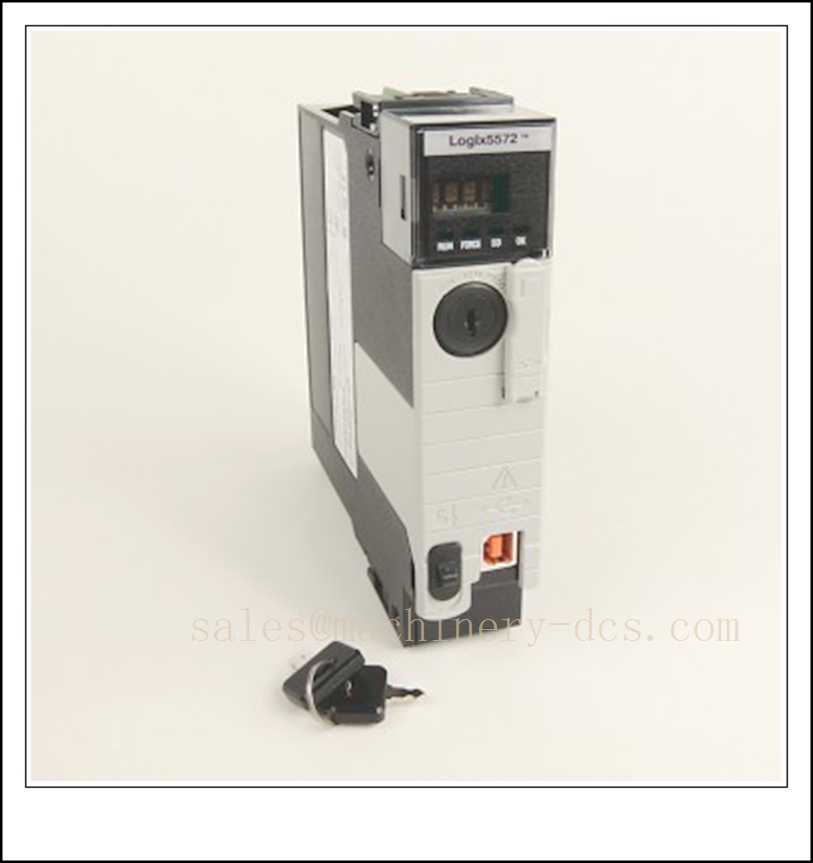
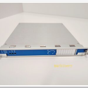
1756-RM2
Core Product Information
| Parameter | Detailed Specification |
|---|---|
| Official Part Number | 1756-RM2 (Catalog ID: 186850) |
| Manufacturer | Allen-Bradley (Rockwell Automation) |
| Product Series | ControlLogix Enhanced Redundancy Module |
| Device Type | Controller Redundancy Synchronization Hot-Standard Unit |
| Mounting Method | Single-slot installation in standard 1756 ControlLogix chassis |
| Compatible Controllers | Full ControlLogix 5570/5580 (L7/L8 series) master units |
| Required Sync Cables | 1756-RMC1 (1m), 1756-RMC3 (3m), 1756-RMC10 (10m) dedicated fiber patch cords |
| Configuration Software | Studio 5000 Logix Designer (supports firmware V20 and later) |
| Warranty | 1-year original factory standard warranty |
| Typical Use Cases | Mission-critical process redundancy, zero-downtime control system construction, legacy redundant system retrofitting |
Key Technical Specifications
Synchronization & Communication Performance
- Transmission Medium: Full fiber-optic redundant link with dual independent transmit/receive channels
- Communication Rate: 1000Mbps gigabit-class high-speed synchronization, fully compliant with 1000BASE-LX fiber standards
- Max Transmission Distance: Up to 10km using 8.5/125μm single-mode fiber
- Synchronization Mechanism: Real-time program mirroring, hot data backup, event-level interaction, and timestamp alignment between primary and secondary controllers
- Switching Performance: Millisecond-level bumpless failover with zero data loss and no process disruption; system scan cycle overhead reduced by up to 35% compared to legacy RM modules
- Supported Protocols: CIP (Common Industrial Protocol), EtherNet/IP, ControlNet, DeviceNet
Electrical & Power Characteristics
- Backplane Current Draw: 1.16A @ 5.1V DC, 3.4mA @ 24V DC
- Max Power Consumption: 6W total, with heat dissipation rated at 21 BTU/hour
- Power Supply: Powered entirely via the ControlLogix chassis backplane, no external auxiliary power required
- Isolation Design: Full electrical isolation on fiber links, eliminating common-mode interference and ground loop current issues that degrade sync stability
Physical & Environmental Ratings
- Dimensions: 139.7mm × 132.1mm × 71.1mm (L×H×W)
- Net Weight: ~0.29kg
- Fiber Connector Type: Duplex LC interface with secure latching for reliable field connections
- Status Indicators: Multi-color integrated LEDs that clearly display sync health, run status, fault conditions, and primary/secondary role
- Ingress Protection: IP20, optimized for sealed control cabinet operation
- Operating Temperature: 0°C to +60°C under full industrial load
- Storage Temperature: -40°C to +85°C
- Humidity Tolerance: 5% to 95% non-condensing
- Environmental Compliance: Meets IEC industrial vibration/shock standards, G3 corrosion resistance, and strict EMC requirements for high-electromagnetic-interference environments with dense variable-frequency drives and motors
Core Functional Advantages
- Gigabit Fiber Ultra-Fast Synchronization: The dedicated 1000Mbps fiber architecture maintains real-time data mirroring between redundant controllers, completing failover in milliseconds to guarantee continuous process operation even during sudden hardware anomalies.
- Optimized Scan Cycle Efficiency: The next-generation enhanced redundancy algorithm drastically cuts synchronization overhead, making the module fully compatible with large-scale programs, high-density I/O configurations, and complex multi-loop process systems.
- Robust Anti-Interference Performance: The fully isolated fiber link completely blocks electrical common-mode noise, ground potential differences, and electromagnetic crosstalk, ensuring zero sync data drift or packet loss in harsh industrial field conditions.
- Intuitive Visual Diagnostics: Built-in status LEDs allow on-site maintenance teams to instantly identify link faults, sync failures, or module anomalies, drastically reducing mean time to repair (MTTR) during troubleshooting.
- Seamless Backward Compatibility: It fits directly into all existing 1756-series ControlLogix chassis, enabling drop-in upgrades for legacy redundant systems without modifying existing master controllers or I/O hardware.
- 24/7 Uninterrupted Operation: The low-power, low-thermal hardware design supports non-stop redundant standby for full calendar years, delivering all-weather fault tolerance for critical production assets.
Recommended Compatible Allen-Bradley Models
- 1756-L71 ControlLogix 5570 Controller
- 1756-L72 ControlLogix 5570 Controller
- 1756-L73 ControlLogix 5570 Controller
- 1756-L75 ControlLogix 5570 Controller
- 1756-L81E ControlLogix 5580 Controller
- 1756-L82E ControlLogix 5580 Controller
- 1756-L83E ControlLogix 5580 Controller
- 1756-L85E ControlLogix 5580 Controller
Compatibility Notes & Installation Pitfalls
- Mandatory Pairing Rule: The 1756-RM2 must be deployed in matched pairs, with one unit installed in each of the two redundant ControlLogix chassis to establish the full synchronization link.
- Cable Compatibility Alert: Never use generic commercial fiber patch cords; only official 1756-RMC series sync cables are validated to meet timing, wavelength, and mechanical locking requirements for stable long-term operation.
- Firmware Version Check: The redundant system must run Logix firmware V20 or newer; mixing legacy V19 or earlier firmware with 1756-RM2 will cause sync failures and unexpected system behavior.
- Slot Placement Flexibility: The module can be inserted into any empty slot in the 1756 chassis, no dedicated slot position is required for normal operation.
- SIL 2 Safety Qualification: When paired with supported L7/L8 controllers, the 1756-RM2 architecture meets Safety Integrity Level 2 requirements for safety-related industrial applications.
Standard Operating Procedure (SOP) for Deployment
- Power off both primary and secondary ControlLogix chassis, then seat one 1756-RM2 module into an available slot in each chassis, securing the integrated chassis latch to lock the unit in place.
- Use the specified 1756-RMC fiber cable to connect the two fiber ports on the paired 1756-RM2 modules, confirming the LC connectors are fully latched.
- Launch Studio 5000 Logix Designer, configure the redundancy properties for both controllers, assign primary/secondary roles, and validate the sync path in the project tree.
- Download the identical project program to both the primary and secondary controllers, then power up the primary chassis first, followed by the secondary chassis.
- Observe the module status LEDs: confirm the “Sync” indicator turns solid green, verifying full program and data mirroring between the two units.
- Perform a manual failover test to validate bumpless switchover, confirm no process tags are lost, and document the full redundancy health status for site maintenance records.
Typical Industrial Application Scenarios
The 1756-RM2 is widely deployed in high-availability automation segments where unplanned downtime carries severe operational or safety consequences, including continuous chemical production lines, power plant auxiliary control systems, municipal water treatment networks, energy management platforms, heavy-industry critical process lines, and large-scale manufacturing production lines.

 Send an Email