
Description
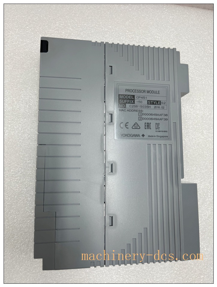
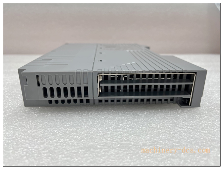
Yokogawa CP451‑50 Processor Module
Product Title
Yokogawa CP451‑50 Processor Module, Core CPU for CENTUM‑VP DCS Field Control Unit (FCU), Hot‑Standby Redundancy Supported
Product Core Overview
The CP451‑50 is the main processor module for Yokogawa CENTUM‑VP distributed control system, executing process control algorithms, sequence logic, data acquisition and system management for the FCU rack. It supports 1:1 hot‑standby redundancy, bumpless switch‑over upon primary CPU failure to guarantee continuous process operation.
This processor communicates with I/O node units via ESB bus / ER bus, handles PID loops, interlock logic, alarm & event management, and exchanges real‑time data with operator stations over Vnet/IP control network. On‑board hardware self‑diagnostics continuously monitor CPU health, backplane communication, memory integrity and network status, and report hardware faults to the HMI system. The CP451‑50 is widely adopted for petrochemical, refinery, power plant and chemical batch‑process critical control applications.
Notes:
- The suffix‑50 stands for standard basic version, non‑explosion‑proof design for indoor cabinet installation.
- Redundant FCU rack requires two CP451‑50 modules plus matched redundant power supply units.
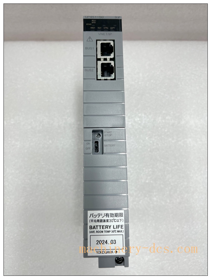
- Battery‑backup memory preserves process data and failure logs during short‑term power loss.
Main Technical Specifications
| Item | Technical Parameter |
|---|---|
| Part Number | CP451‑50 |
| Manufacturer | Yokogawa Electric |
| Applicable System | CENTUM‑VP DCS, FCU rack (AFV300 / AFV400 series) |
| Processor | 32‑bit RISC processor |
| Control Cycle | Minimum 20 ms, typical 100 ms |
| Max PID Control Loops | Up to 4000 loops |
| Memory | Program memory 256 MB; Data memory 128 MB; Battery‑backed RAM |
| Redundancy Mode | 1:1 hot‑standby redundancy, bumpless switch‑over |
| System Bus | ESB Bus:128 Mbps; ER Bus:10 Mbps; Supports fiber‑optic ESB extension |
| Control Network | Dual Vnet/IP Ethernet interfaces |
| Node Unit Capacity | Max 14 node units per FCU (9 for standard ESB bus) |
| Power Supply | Powered by rack backplane 5 VDC |
| Power Consumption | Typical 15 W |
| Operating Temperature | 0 °C ~ +50 °C |
| Storage Temperature | −20 °C ~ +70 °C |
| Relative Humidity | 5 %‑95 % non‑condensing |
| Mounting | Hot‑plug‑in slot inside FCU rack |
| Hot‑swap | Supported under redundant configuration |
| Weight | 0.7 kg |
| Dimension (W×H×D) | 50 mm × 200 mm × 150 mm |
| Status Indicators | PWR, CPU, ALM, HRDY, Vnet link status LEDs |
Related Series & Model Recommendations (8+ Models)
- CP451‑50: Standard processor module, base version for CENTUM‑VP FCU
- CP451‑10: Low‑performance variant of series, fewer control loops capacity
- CP401‑50: Early‑generation CPU module for CENTUM‑VP FCU
- PW482: Redundant power supply unit for FCU rack, matched for ‑50 deployment
- AFV401‑S: FCU base rack chassis for housing ‑50 processor modules
- SB401‑10: ESB bus interface node unit for connecting remote I/O racks
- LFS1550: FCU capacity expansion software package, increase maximum node‑unit quantity
- CP461‑50: Higher‑performance successor processor module for CENTUM‑VP
- FIO‑VNET/IP: Vnet‑IP communication interface adapter for DCS system network
Professional Quality Control & Factory Test Procedures
- Visual & Mechanical Incoming Inspection: Inspect housing, edge connector, front‑panel LED indicators, label marking; record serial‑number for full‑lifecycle traceability. Anti‑static inspection for PCB assembly.
- Power‑supply Stress Test: Verify stable operation under full backplane voltage tolerance range, simulate voltage drop and surge disturbance.
- Memory Full‑Coverage Test: Complete RAM/ROM read‑write test, verify battery‑backup memory retention performance under power‑off condition.
- Self‑diagnostic Function Test: Simulate memory parity error, bus communication failure, network port fault, confirm LED alarm and fault‑report output.
- Bus Communication Performance Test: ESB / ER bus interface test, verify stable data exchange with multiple node‑units.
- Redundancy Switch‑over Test: Install dual ‑50 modules in FCU rack; validate bumpless primary‑standby switch‑over, data synchronization consistency.
- Control Loop Execution Test: Load large‑quantity PID & interlock logic, verify control cycle timing and algorithm calculation accuracy.
- Vnet/IP Network Communication Test: Dual network ports communication test, simulate single‑network link failure, check network redundancy function.
- Environmental Stress Screening: Temperature‑cycle test over whole operating‑temperature range, damp‑heat test.
- EMC Electromagnetic Compatibility Test: Surge, EFT and electrostatic discharge test according to industrial IEC standards.
- Final Full‑function Validation & Archiving: Complete system‑level acceptance test; bind all test‑reports with unit serial‑number before factory release.
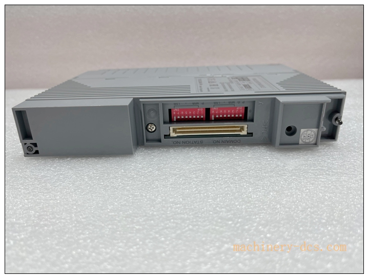
CP451-50
New Module Installation & Commissioning Guide
6.1 Pre‑installation Preparation
Check module for transit damage, confirm part‑number and serial‑number match purchase documents. Verify FCU rack hardware revision, firmware compatibility and CENTUM‑VP software version. Prepare anti‑static wrist‑strap and gloves. For redundant configuration, confirm paired CPU firmware revision consistency. Review system drawings for slot assignment.
6.2 Mechanical Installation
For redundant running system: hot‑swap is permitted only when the counterpart standby CPU keeps healthy HRDY status. Insert ‑50 firmly into the designated FCU rack slot, lock the module latch. Do not force insertion to avoid backplane connector damage. For first‑time commissioning, power‑off the FCU rack before module insertion.
6.3 Wiring & Backplane Check
Confirm FCU rack redundant power supply units PW482 are correctly installed. Check ESB bus and Vnet/IP dual‑Ethernet cables connection, use shielded industrial Ethernet cables. Complete cabinet protective grounding, grounding resistance ≤4 Ω. Separate signal cables from high‑power power cables.
6.4 System Commissioning
- Power‑on FCU rack, observe front‑panel LED sequence: PWR LED solid green after power‑on, complete power‑on self‑test.
- Log on to CENTUM‑VP engineering station, confirm system recognizes ‑50 processor module.
- Verify firmware version matches project requirement, perform firmware upgrade if necessary.
- Download system database, control configuration and application logic to FCU processor.
- For redundant CPU pair: check primary‑standby synchronization status, execute manual redundancy switch‑over test, confirm no process disturbance.
- Verify ESB‑bus I/O node‑unit communication status, check PID loop execution and alarm‑event logging function.
- Simulate CPU hardware fault condition, confirm fault alarm is uploaded to operator HIS station.
- Backup FCU configuration database, put processor into formal operation.
Application Scenarios & Product Features
7.1 Application Scenarios
‑50 is deployed in CENTUM‑VP DCS for large‑scale continuous process industries: oil refinery, petrochemical complex, chemical plant, thermal power plant, coal‑chemical, pulp‑and‑paper and pharmaceutical batch‑production plants. It serves as field control core for critical‑process loops, interlock and sequence control.
7.2 Core Product Features
- 1:1 Hot‑Standby Redundancy: Bumpless switch‑over, maximize system availability for non‑stop process production.
- High‑capacity Control Processing: Supports thousands of PID control loops, complex sequence and interlock logic.
- Dual‑redundant Communication: Dual Vnet/IP control network, ESB field‑bus redundancy capability.
- Complete Hardware Self‑diagnostics: Real‑time detection for memory, bus, network and internal hardware faults, alarm reporting.
- Battery‑backed Memory: Preserve runtime data and fault logs during power interruption.
- Hot‑swap Support: Module replacement without rack power‑down under redundant configuration.
- Deterministic Control Cycle: Stable short control cycle for high‑speed process‑control requirements.
- Industrial‑grade Reliability: Strict environmental and EMC compliance for harsh plant cabinet environments.
Frequently Asked Questions (FAQ)
Q1: Can ‑50 work in single CPU mode without redundancy? A: Yes, single‑CPU configuration is supported, but there is no fault‑tolerance capability. When CPU fails, the whole FCU will lose control output. Redundant dual‑CPU configuration is strongly recommended for critical production loops.
Q2: Is hot‑swap available for ‑50? A: Hot‑swap is only valid under 1:1 redundant configuration. Confirm the standby CPU is in healthy HRDY ready status via HIS station before removing the faulty unit. Hot‑swap is forbidden in single‑CPU mode, which will cause process outage.
Q3: What causes HRDY LED off on ‑50? A: Common root‑causes: firmware mismatch, backplane connector poor contact, ESB‑bus communication failure, memory error, power supply abnormality, incompatible CENTUM‑VP software version. Swap module to known‑good slot to distinguish module fault or rack‑backplane fault.
Q4: Can I replace ‑50 with ‑10 directly? A: Not recommended. They differ in processing capacity and firmware requirement. Verify hardware revision, firmware compatibility and project database before cross‑model replacement, otherwise communication or control‑loop loading failure may appear.
Q5: How many I/O node units can one ‑50 FCU support? A: Standard ESB bus supports up to 9 node‑units. With LFS1550 expansion package, maximum expands to 14 node‑units per FCU.
Q6: Can I disassemble and repair ‑50 on‑site? A: No. This is factory‑calibrated integrated DCS hardware. Unauthorized disassembly voids warranty and functional‑safety compliance. Return defective unit to Yokogawa authorized service center.
Q7: What is battery function for ‑50? A: On‑board backup battery preserves RAM runtime data and fault event logs during power loss. Periodically check battery health status; replace battery when low‑battery alarm appears.

 Start Chat


 Send an Email


