
Description
Triconex 8312 175W Redundant 230VAC Input Power Supply Module for Tricon TMR SIS
Product Description
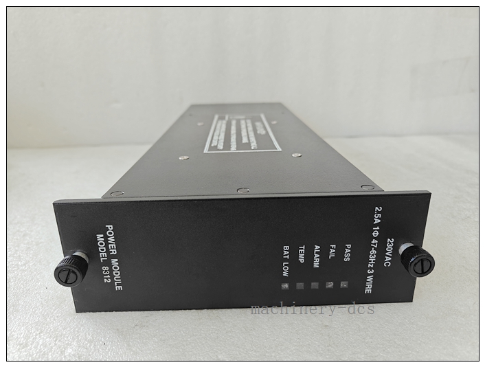
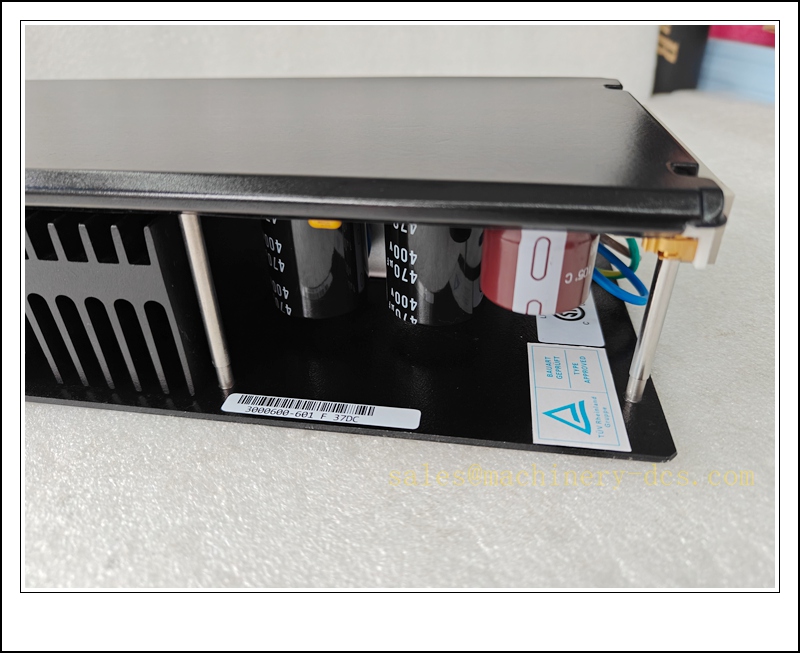
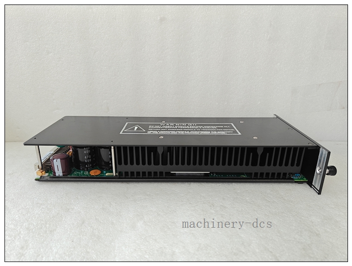
The Triconex 8312 is a high-reliability 175W power supply module designed for the Tricon triple modular redundant safety instrumented system. It accepts 230VAC mains power and converts it into tightly regulated 6.5VDC backplane power to energize Tricon main processors, I/O modules and internal chassis circuits within main racks, expansion racks and RXM remote racks. It is typically deployed in dual redundant configuration; a single unit is capable of supporting the full chassis load independently to eliminate single-point power failure risks for safety functions. Integrated diagnostics and front-panel LED indicators provide status of PASS, internal fault, overtemperature and low battery alarms. Hot-swap replacement is supported when the paired redundant power supply remains healthy, enabling online maintenance without shutting down the safety system. Galvanic isolation between AC input and low-voltage backplane protects sensitive TMR electronics from electrical surges and ground transients.
TRICONEX 8312
Technical Specifications
- Brand: Triconex (Schneider Electric / Invensys Legacy)
- Model: 8312
- Module Type: Redundant Chassis Power Supply
- Rated Output Power: 175 W continuous at 60°C ambient
- Output: 6.5 VDC, ±1% regulation, max 27 A
- AC Input: 180–250 VAC, 47–63 Hz
- Hold-up Time: ≥20 ms upon input power loss
- Protection: Overvoltage, overcurrent, short-circuit protection, thermal shutdown, input surge filtering
- Internal Fuse: 5 A time-delay non-field-replaceable fuse
- Status Indicators: PASS, FAIL, ALARM, TEMP, BAT LOW LED indicators
- Alarm Interface: SPDT dry fault relay contact
- Galvanic Isolation: 1500 VDC input-to-backplane isolation
- Hot Swap: Supported under redundant dual power configuration
- Operating Temperature: 0 °C to +60 °C
- Storage Temperature: -40 °C to +85 °C
- Relative Humidity: 5%–95%, non-condensing
- Safety Certification: SIL 3 capable per IEC 61508, ATEX Zone 2, UL, CE
- Compatible Chassis: Tricon 7-slot and 15-slot main chassis, expansion chassis, RXM remote chassis
- Approximate Weight: 3.8 kg
Application Scenarios
- Petrochemical and refinery Tricon ESD racks powered by 230VAC plant mains
- Onshore and offshore oil & gas fire and gas safety instrumented systems
- Power plant boiler protection, turbine trip and burner management SIS cabinets
- LNG terminals and cryogenic SIL 3 safety control panels supplied by 230VAC UPS
- Remote pipeline safety control cabinets with 230VAC site power
- Continuous chemical process critical safety control racks
- Hazardous Class I Div 2 / Zone 2 SIS control panels
- Spare replacement and maintenance for existing Tricon 3000-series installations
8 Related Triconex Model Recommendations
- 8310 – 120VAC/VDC Input Tricon Power Supply Module
- 8311 – 24VDC Input Tricon Power Supply Module
- 3805E – Tricon Main Processor Module
- 3703E – 8-Channel Analog Input Module
- 3704E – 8-Channel Analog Output Module
- 3503E – 32-Channel 24VDC Digital Input Module
- 3625 – 32-Channel Supervised Digital Output Module
- 4351B – Tricon Communication Module (TCM)
Compatibility & Installation Pitfalls
Compatibility
- Designed only for dedicated power slots of Tricon TMR chassis; incompatible with Trident chassis and Bently Nevada 3500 racks.
- This is the 230VAC input variant; do not interchange with 8310 (120VAC/VDC) or 8311 (24VDC).
- Dual redundant installation is the standard SIL design; single-unit operation is only permitted for temporary maintenance.
- The power slot is mechanically keyed and cannot be fitted into I/O, processor or communication slots.
- This module provides only chassis backplane logic power; it does not supply field loop power for transmitters or solenoid valves.
- SIL 3 safety integrity relies on redundant power architecture and a healthy TMR processor triplet.
Installation Pitfalls
- Hot-swap is permitted only when the second redundant power unit is healthy and can carry the full chassis load. Never remove the last active power source while the SIS is online.
- Do not mix 8310, 8311 and 8312 within the same redundant power pair. Mismatched input types will trigger alarms and system instability.
- 230VAC high-voltage wiring must comply with hazardous area standards. Install surge suppression for sites prone to voltage transients.
- The BAT LOW alarm monitors the chassis backup battery; it is a maintenance alarm and not inherently a module fault.
- The TEMP alarm indicates excessive internal temperature. Check cabinet ventilation, cooling fans and ambient temperature before acknowledging the alarm.
- The internal 5A time-delay fuse cannot be replaced on site. Repeated fuse trips point to backplane short or overload and require root-cause investigation.
- Do not exceed the total chassis power rating. Adding excessive I/O modules may overload the 175W capacity of each supply.
- Dry fault relay contacts are signal-level contacts; they must not be used to switch high-current loads directly.
TRICONEX 8312
Standard Operating Procedure (SOP)
SOP for 8312 Power Supply Module Inspection, Installation and Functional Test
- Pre-Installation Inspection Inspect the module for physical damage, deformed connectors or contamination. Confirm the part number 8312 and verify the required 230VAC input specification. Review chassis load calculations, redundant power layout and site AC power distribution drawings. Apply lockout-tagout to the SIS AC feed if isolating the last live power supply.
- Rack Installation Power down the chassis if removing the final operational power unit. Insert the 8312 into the dedicated chassis power slot and secure the module fasteners. Terminate the 230VAC input wiring and fault alarm relay wiring at the backplane terminals. Separate high-voltage AC power cabling from low-level analog and discrete I/O wiring and implement EMC shielding per approved SIS drawings.
- Power-on Verification Restore 230VAC mains power to the module. Confirm the PASS LED illuminates with no active FAIL, TEMP or BAT LOW alarms. Verify the redundant paired supply stays synchronized and does not trigger load alarms. Resolve wiring, input voltage range or grounding issues if alarms persist.
- Load and Diagnostic Test With the rack online, confirm main processors and all I/O modules boot and communicate normally. Simulate loss of the redundant partner supply to verify the single 8312 takes the full chassis load without SIS trip. Confirm the fault relay changes state when the module is de-energized or a fault is induced. Record alarm and load transfer performance in the SIS maintenance log.
- System-Wide Interlock Verification Validate all safety logic, analog and discrete I/O channels remain operational during automatic transfer between redundant power supplies. Confirm a single power supply fault generates only a maintenance alarm and will not cause unintended ESD shutdown.
- Return to Service Clear all temporary fault latches and alarm acknowledgements. Remove lockout-tagout as applicable. Monitor module LED status, chassis temperature and AC input quality for the required observation period. Notify operations that redundant SIS power is restored.
- Periodic Maintenance and Replacement During planned outages, inspect terminal torque, cable insulation and cabinet cooling performance. Execute redundant power transfer testing per the site SIS proof-test schedule. If the 8312 presents persistent non-resettable faults, confirm the second supply is fully healthy before hot-swap. After replacement, verify PASS status, load sharing and alarm relay operation before releasing the rack to safety duty.

 Start Chat


 Send an Email


