
Description
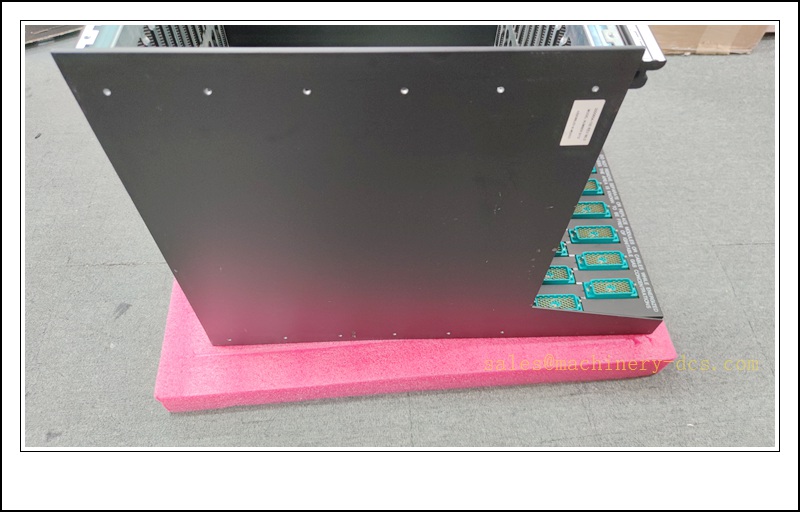
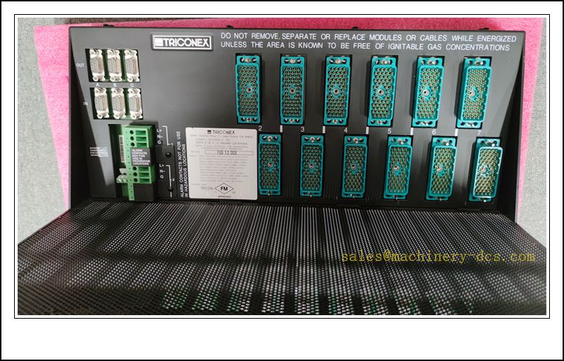
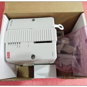
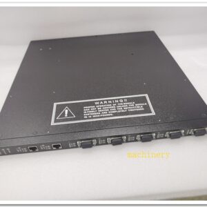
TRICONEX 8112 Spare Board | Industrial Control System Automation Spare Part
Product Brief Introduction
The TRICONEX 8112 is a critical spare circuit board designed for Triconex triple modular redundant (TMR) safety instrumented systems (SIS), widely deployed in high-risk process industries including oil & gas, petrochemical, power generation, and chemical plants. Adopting mature TMR fault-tolerant architecture, this board supports hot swap without system shutdown, ensures continuous safe operation of the safety system, and mitigates unplanned downtime caused by component failure. It is a genuine replacement spare for the Tricon safety controller rack, featuring high electromagnetic compatibility, long service life, and strict compliance with global functional safety standards.
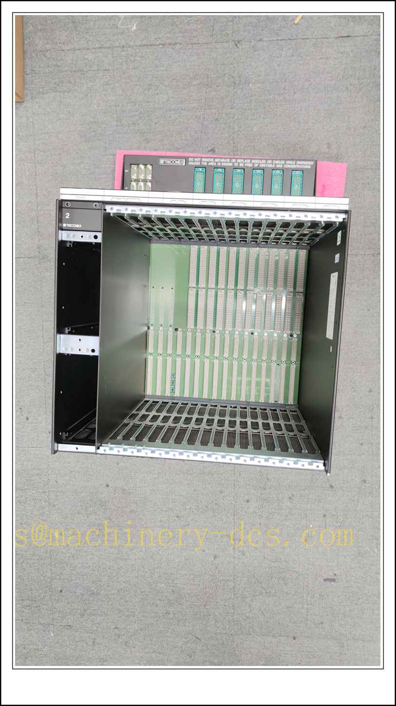
TRICONEX 8112
Key Technical Specifications
- Brand: TRICONEX
- Part Number: 8112
- Architecture: Triple Modular Redundant (TMR)
- Functional Safety Level: SIL 3 capable
- Hot Swappable: Yes (online replacement, no rack power-off required)
- Operating Temperature Range: 0 °C ~ +60 °C
- Storage Temperature Range: -40 °C ~ +85 °C
- Relative Humidity: 5% ~ 95% non-condensing
- EMC Compliance: IEC 61000 series
- Mounting: Installed in standard Triconex chassis rack
- Enclosure Class: Industrial grade, for indoor control cabinet installation
- Service Life: ≥15 years under rated operating conditions
- Communication Interface: Matches native Triconex backplane bus
- Fault Diagnosis: Built-in self-test (BIST), on-board fault LED indicator
Quality Control Procedure
- Incoming Visual & Dimensional Inspection: Check appearance, labeling, solder joints, connectors for damage, corrosion or offset.
- Component Verification: Confirm original electronic components, screen counterfeit or substituted parts.
- Bench Functional Test: Power on and run full BIST to verify bus communication, signal channel integrity and fault alarm function.
- TMR Logic Simulation Test: Load safety logic simulation to validate redundant voting function.
- Burn-in Test: Continuous powered aging test under rated temperature for stress screening.
- EMC Pre-check: Verify anti-interference performance against industrial noise environment.
- Final Calibration & Labeling: Record serial number and test report, attach qualified label.
- Packing Inspection: Use anti-static shielding bag + shockproof foam for ESD protection before shipment.
- Archive Test Record: All test logs reserved for traceability.
Related TRICONEX Model & Part Number Recommendations (15 pcs)
- TRICONEX 3008 Main Processor Module
- TRICONEX 3009 Main Processor Module
- TRICONEX 3604E Digital Output Module
- TRICONEX 3625 Digital Input Module
- TRICONEX 3700A Analog Input Module
- TRICONEX 3703E Analog Output Module
- TRICONEX 4101 Communication Module
- TRICONEX 4351 Remote Interface Module
- TRICONEX 8101 Chassis Backplane
- TRICONEX 8111 Power Supply Board
- TRICONEX 8300 Power Supply Module
- TRICONEX 9661 Termination Board
- TRICONEX 9761 Terminal Block Assembly
- TRICONEX 4000 Communication Adapter
- TRICONEX 3501 Tricon Expansion Interface
Frequently Asked Questions (FAQ)
Q1: Can TRICONEX 8112 be replaced online while the SIS system keeps running?A1: Yes, it supports hot-swap design. Follow standard maintenance procedure to replace without system shutdown.
Q2: What safety standard does TRICONEX 8112 comply with?A2: It is designed for SIL3 safety loop application, meets IEC 61508 functional safety requirements.
Q3: Is this board compatible with all Triconex Tricon racks?A3: It fits corresponding Tricon series racks. Confirm rack firmware version before ordering for compatibility.
Q4: How long is the warranty period?A4: Standard warranty is 12 months after delivery. Extended warranty service is available upon request.
Q5: Does static electricity damage this spare board easily?A5: Yes. Always wear ESD wrist strap and use anti-static packaging during handling and installation.
Q6: Can it be repaired locally if faulty?A6: Not recommended. It is a safety critical board; return to authorized supplier for professional test & repair.
Installation & Configuration Guide
- Pre-installation Preparation
- Power status: Confirm the target rack is in safe maintenance state; confirm hot-swap permission from DCS/SIS operator.
- Prepare tools: ESD wrist strap, insulated screwdriver, spare anti-static bag.
- Check the new 8112 board: Confirm part number, no physical damage, test label valid.
- Removal of Old Board
- Locate the target slot of 8112 inside chassis.
- Release the front latch of the board, slowly pull the board out along the guide rail.
- Immediately put the faulty board into an ESD bag.
- New Board Insertion
- Wear ESD wrist strap all the time.
- Align the circuit board connector with backplane slot, push steadily until fully seated.
- Lock the front latch to fix the board.
- Power-on & Configuration Verification
- The system will automatically detect the new board and run built-in self-test.
- Observe front panel LED indicators: Green = normal; Red = fault alarm.
- Log into Triconex TriStation software, check hardware tree, confirm the board is recognized.
- Download or verify safety logic if required; check redundant voting status.
- Post-installation Handover
- Clear fault alarm records, record serial number, replacement time in maintenance log.
- Perform loop test for related safety points, confirm no safety function loss.
- Restore system to normal operation mode and inform operation team.
- Important Notes
- Do not insert or extract the board without ESD protection.
- Do not touch gold-plated connectors directly by hand.
- If the board reports constant fault after installation, stop operation and contact supplier for technical support.

 Send an Email