
Description
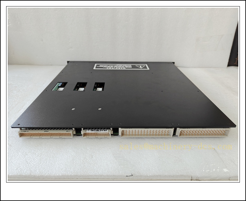
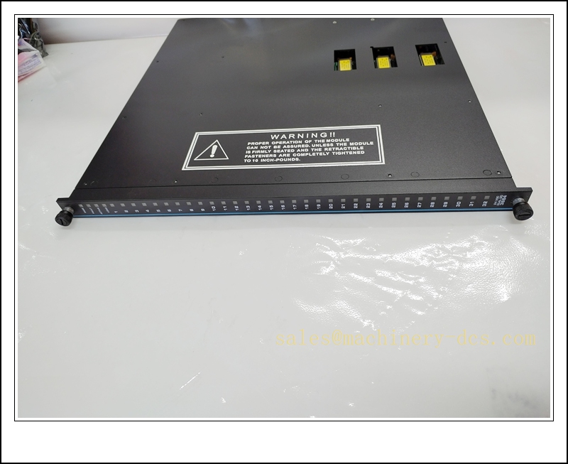
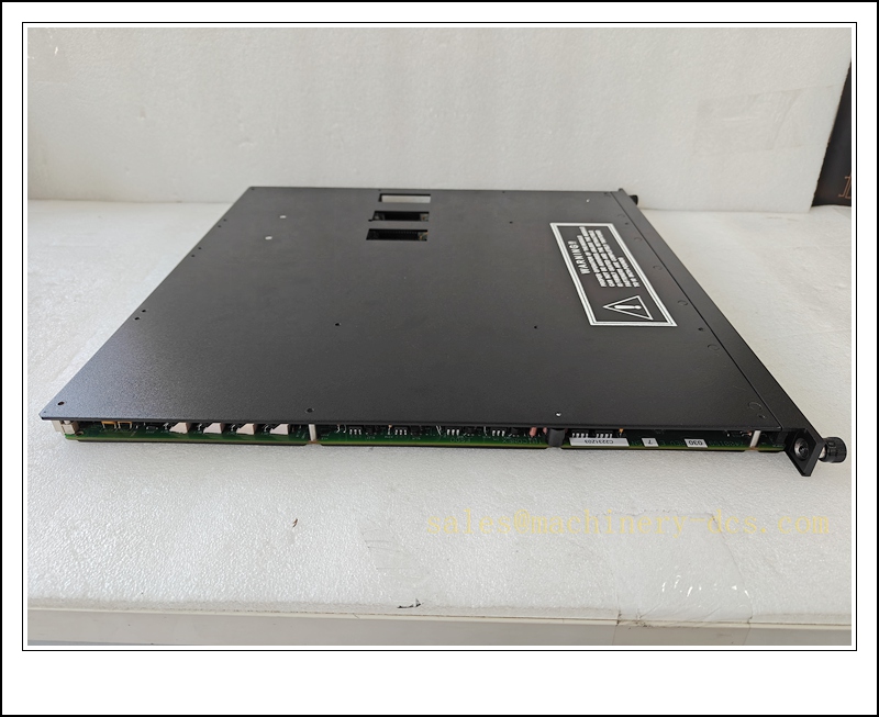
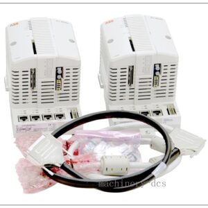
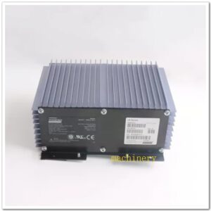
TRICONEX 3664 Dual Digital Output (DDO) 32-Channel 24VDC Supervised Safety Module for Tricon TMR SIS
Product Description
The TRICONEX 3664 is a high-density Dual Digital Output safety module built for the Tricon Triple Modular Redundant (TMR) safety instrumented system. It delivers 32 commoned 24VDC discrete outputs for safety-critical field actuators, solenoid valves and trip relays, mainly applied in de-energize-to-trip safety logic. This module adopts dual-path output design with 2oo3 hardware voting from the Tricon main processor; single internal fault will be isolated without causing spurious trip or loss of safe-state control. It provides per-channel supervised loop diagnostics to detect open load, short-circuit and wiring faults. Hot-swap capability allows online replacement while the SIS rack remains operational, minimizing plant downtime. The module communicates with Tricon main processors via the proprietary backplane bus and is configured using TriStation 1131 software, certified to IEC 61508 for SIL3 safety loops.
Technical Specifications
- Brand: TRICONEX (Schneider Electric)
- Part Number: 3664
- Module Type: Dual Digital Output (DDO)
- Channel Count: 32 commoned output points
- Nominal Field Voltage: 24 VDC, operating range 16–30 VDC, max transient 36 VDC
- Per-Point Rating: 2 A continuous, 10 A surge for 10 ms
- Typical Voltage Drop: <1.5 VDC
- Max Load Leakage: 2 mA
- Isolation Rating: 1500 VDC between field circuit and logic side
- Diagnostics: Per-channel loop supervision, open load, short circuit, backplane communication fault, module self-test
- Communication: Tricon proprietary backplane bus
- Configuration Software: TriStation 1131
- Safety Certification: IEC 61508 SIL 3, IEC 61511
- Operating Temperature: 0 °C ~ +60 °C
- Storage Temperature: -20 °C ~ +70 °C
- Relative Humidity: 5% ~ 95%, non-condensing
- Mounting: Slot mounting inside Tricon chassis
- Approximate Weight: 2.46 kg
TRICONEX 3664
Application Scenarios
- Petrochemical and refinery ESD emergency shutdown solenoid control
- Offshore oil & gas platform safety interlock and HIPPS valve driving
- Power plant boiler, turbine and BMS burner management trip outputs
- LNG terminal and cryogenic process safety shutdown systems
- Chemical reactor safety interlock, alarm relay and isolation valve control
- Mining and pipeline overpressure protection safety actuation
- Fertilizer and hydrogen process critical safety layer control
- Spare maintenance and retrofitting of legacy Tricon Tricon SIS racks
8 Related TRICONEX Model Recommendations
- 3674 – TRICONEX DDO Digital Output Module
- 3503E – TRICONEX Digital Input Module
- 3721 – TRICONEX Analog Input Module
- 4351B – TRICONEX Communication Interface Module
- 8110 – Tricon Main Processor Module
- 3805E – TRICONEX Digital Output Module
- 3008 – Tricon Power Supply Module
- 4108 – Tricon Backplane Interface Module
Compatibility & Installation Pitfalls
Compatibility
- Designed exclusively for Tricon TMR SIS racks; not compatible with other Triconex families such as Trident or DCS controllers.
- Works with Tricon main processor series and TriStation 1131 programming software.
- Requires matched field termination panel for 32-channel commoned return wiring; mismatched termination assemblies disable supervised diagnostics.
- Optimized for de-energize-to-trip safety logic; it is not the preferred choice for energize-to-trip critical loops without safety review.
- Backplane firmware revision must support DDO 3664; outdated firmware triggers bus communication faults.
- Field loads must satisfy the minimum load requirement for loop supervision; very low-current coils may cause false open-load alarms.
Installation Pitfalls
- Confirm the SIS logic and interlock status before hot swap; hot replacement does not remove process hazards and should follow plant work permit rules.
- Field 24VDC output cables must be segregated from high-power motor and VFD cables; poor separation leads to EMI-induced spurious state changes.
- Verify commoned return wiring at the termination panel; incorrect return grouping causes cross-channel interference and diagnostic misreads.
- Supervision function depends on proper coil impedance; test each solenoid for minimum load current prior to commissioning.
- Do not exceed the 2A continuous per-channel rating; overcurrent will latch the channel into fault state and may damage output circuitry.
- Check chassis cooling airflow; blocked rack ventilation or excessive cabinet temperature leads to module overheat and loss of voting function.
- Termination wiring torque must follow TRICONEX drawings; loose terminals produce intermittent load faults that are hard to reproduce.
- After replacement, download the validated TriStation application and re-test each output channel; a new module does not automatically retain channel calibration or supervision settings.
TRICONEX 3664
Standard Operating Procedure (SOP)
SOP for 3664 DDO Safety Module Inspection, Installation and Functional Test
- Pre-Installation Inspection Examine the module for physical damage, bent connectors, burnt components or contamination. Confirm part number 3664. Verify compatibility with Tricon chassis, main processor firmware and matched termination panel. Review safety logic drawings, field solenoid load data and work permit. Apply lockout-tagout to associated field safety circuits and isolate field power where required.
- Chassis Installation Insert the 3664 module into the designated empty slot of the Tricon rack and lock the module latches. Connect the ribbon cable to the corresponding field termination assembly. Terminate 24VDC solenoid and relay field wiring at the panel. Separate safety output cables from high-energy power wiring and apply EMC grounding as per TRICONEX specifications.
- Software Configuration Launch TriStation 1131 and connect online to the Tricon rack. Add and map the 3664 within the I/O configuration, enable per-channel load supervision and define safe-state behaviour for each point. Download the validated safety application to the Tricon processors. Save the application and I/O map to offline backup. Resolve backplane bus and module identification alarms before field testing.
- Channel and Diagnostic Test Force each output channel from TriStation, confirm solenoid or relay state changes and monitor supervised load status. Simulate open load and short-circuit conditions to verify fault alarm reporting. Confirm TMR voting maintains safe state when a single module path fault is injected. Record channel response and diagnostic behaviour in the safety test log.
- Safety Interlock Commissioning Release field isolation only after point-level testing passes. Execute full safety interlock test sequences, initiate trip conditions and verify the module drives outputs to the defined de-energized safe state. Confirm faults trigger diagnostic alerts without uncontrolled actuator energization. Cross-check trip status to DCS and alarm systems.
- Return to Service Reset fault latches and acknowledge diagnostic alarms. Remove lockout-tagout and close the work permit. Monitor module health, backplane status and channel supervision alarms during the supervised observation window. Notify operations that the 3664 safety output module is ready for normal process operation.
- Periodic Maintenance and Replacement During scheduled SIS proof-test, inspect module LEDs, termination torque, cable shielding and load supervision. Execute the plant safety proof-test procedure for all output loops. If persistent unrecoverable module or bus faults occur, apply work permit and circuit isolation before hot swap. After replacement, reload the TriStation application, repeat full channel and interlock proof-test before releasing the safety function online.

 Start Chat


 Send an Email


