
Description
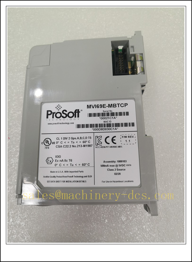
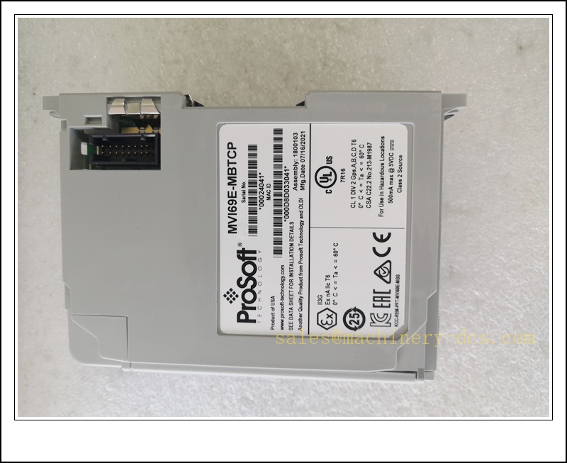
ProSoft MVI69E-MBTCP Enhanced Modbus TCP/IP Communication Module for Allen‑Bradley CompactLogix 1769 Chassis
Product Description
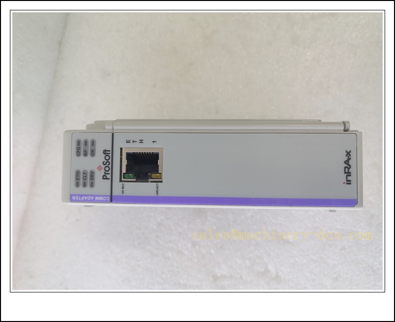
The MVI69E-MBTCP is a single-slot in-chassis co-processor communication module designed for the CompactLogix 1769 platform. It delivers high-performance Modbus TCP/IP connectivity, supporting simultaneous Modbus Client (Master) and Server (Slave) operation to bridge CompactLogix controllers with Modbus TCP field instruments, VFDs, flow transmitters, RTUs and SCADA hosts. Equipped with an integrated 10/100Mbps auto-negotiation Ethernet port, the module offloads Modbus protocol processing from the CompactLogix CPU to minimize PLC scan-time impact. It supports up to 20 Client and 20 Server concurrent connections, with a maximum data capacity of 10,000 16-bit registers. Floating-point data mapping is configurable for Enron, Daniel and other non-standard Modbus floating-point implementations. The module works with ProSoft Configuration Builder and Studio 5000 Add‑On Profile / Add‑On Instruction (AOI), allowing tag-based diagnostics and project configuration saved within the CompactLogix ACD project file. It can operate in legacy mode to migrate configurations from older MVI69-MNET modules.
Technical Specifications
- Brand: ProSoft Technology
- Part Number: MVI69E-MBTCP
- Platform: Allen‑Bradley CompactLogix 1769 Chassis
- Module Form Factor: Single 1769 slot
- Backplane Current Draw: Max 500 mA @ 5 VDC backplane
- Ethernet Interface: 1 × 10/100BASE-T auto-negotiating RJ45
- Modbus Role: Simultaneous Client / Server
- Concurrent Connections: 20 Client sessions, 20 Server sessions
- Maximum Data Capacity: 10,000 16-bit words
- Floating Point: Configurable Enron / Daniel floating-point support
- I/O Transfer Sizes: 60 / 120 / 240 16-bit integers
- Configuration Tool: ProSoft Configuration Builder (PCB)
- Programming Environment: Studio 5000 Logix Designer, AOP + AOI
- Status LEDs: Module Status, Application, Backplane, Ethernet Link/Activity
- Operating Temperature: 0 °C ~ +60 °C
- Storage Temperature: -40 °C ~ +85 °C
- Relative Humidity: 5% ~ 95%, non-condensing
- Mounting: Slot mount in 1769 CompactLogix backplane
- Weight: Approx. 0.18 kg
- Certification: CE, UL, RoHS
MVI69E-MBTCP
Application Scenarios
- Factory automation linking CompactLogix PLC to Modbus TCP variable frequency drives
- Water and wastewater treatment plant instrument communication for flow, level and pH transmitters
- Oil & gas skid control, remote wellsite RTU and pump station data interface
- Building HVAC and chiller plant control with Modbus TCP BMS devices
- Material handling and packaging machinery sensor and actuator network integration
- Power auxiliary equipment monitoring, generator controllers and protection relays
- Retrofit migration from legacy MVI69-MNET Modbus TCP modules on CompactLogix racks
- General industrial SCADA and HMI communication with Modbus TCP field networks
8 Related ProSoft Model Recommendations
- MVI69L-MBTCP – Lite Modbus TCP/IP Module for CompactLogix
- MVI69E-MBS – Modbus Serial (RS485/232) Enhanced Module for CompactLogix
- MVI69-PDPMV1 – PROFIBUS DPV1 Master Module for CompactLogix
- MVI56E-MNET – Modbus TCP Module for ControlLogix 1756 Platform
- MVI69E-PN – PROFINET IO Module for CompactLogix
- MVI69-ADM – Application Development Module for CompactLogix
- MVI46-MBTCP – Modbus TCP Module for SLC 500
- 1769-PA4 – CompactLogix 1769 Rack Power Supply
Compatibility & Installation Pitfalls
Compatibility
- Designed exclusively for CompactLogix 1769 chassis; requires Logix controller firmware Revision 16 or newer. It is not compatible with MicroLogix, ControlLogix 1756 or SLC 500 native backplanes.
- Requires Studio 5000 Add‑On Profile and AOI imported to the project; generic module definition limits diagnostic tag support.
- Legacy mode is available for MVI69-MNET configuration migration, but register mapping and timing parameters must be validated after conversion.
- Supports standard Modbus function codes; non-proprietary Modbus TCP devices only, custom vendor extensions may not function correctly.
- Multiple MVI69E-MBTCP modules can reside in one rack, but each AOI instance must use unique tag names to avoid project conflicts.
- The module uses the 1769 backplane for data exchange; it cannot be used as a standalone network gateway outside the CompactLogix chassis.
Installation Pitfalls
- Power down the 1769 rack before inserting or removing the module; live insertion risks backplane bus damage and module latch-up.
- Apply ESD protection during handling; the PCB is sensitive to electrostatic discharge.
- Use industrial shielded CAT5e/CAT6 Ethernet cable; shared noisy network with VFDs can cause packet loss and intermittent timeouts.
- Static IP addressing is strongly recommended; DHCP may cause loss of communication after power cycling.
- Match Modbus register offset conventions (0-based vs 1-based) between PCB configuration and field devices; this is a common source of swapped or invalid readings.
- Do not overload concurrent connection count; exceeding 20 Client sessions triggers connection refusal and polling failures.
- Verify backplane power budget; adding the module’s 500 mA load must stay within the rating of the 1769 power supply.
- After module replacement, the new unit does not retain configuration; the ACD project and PCB configuration must be downloaded, and AOI tags re-validated.
MVI69E-MBTCP
Standard Operating Procedure (SOP)
SOP for MVI69E-MBTCP Communication Module Inspection, Installation and Functional Test
- Pre-Installation Inspection Examine the module housing, backplane edge connector and Ethernet port for physical damage, bent pins or contamination. Confirm part number MVI69E-MBTCP. Verify CompactLogix controller firmware revision, rack power budget and compatibility with Studio 5000 / ProSoft Configuration Builder versions. Review network drawings and apply lockout-tagout to the 1769 rack power supply.
- Chassis Installation Insert the into the designated empty 1769 rack slot and engage the locking latch. Terminate the Ethernet cable to the module RJ45 port and connect to the industrial Modbus TCP network. Segregate control network from office or non-critical LAN traffic and implement EMC shielding and proper grounding per ProSoft and Rockwell guidelines.
- Project Configuration Restore rack power. Import the Add‑On Profile and AOI into the Studio 5000 project. Open ProSoft Configuration Builder to define Modbus Client polling lists and Server register maps, then export the AOI L5X file and import it into the Logix project. Configure module static IP address, connection limits and floating-point format. Download the validated controller project to the CompactLogix CPU and save a full offline ACD backup. Resolve backplane identification and Ethernet link alarms before field device testing.
- Network and Modbus Communication Test Monitor module status tags and Ethernet link LEDs. Test each defined Modbus Client poll to field devices, validate holding register, input register, coil and discrete input data. Simulate Ethernet cable disconnection and device offline conditions to confirm fault tag and timeout reporting. Record poll latency and fault response in the commissioning log.
- Process Commissioning Enable automatic control logic only after point-level Modbus read/write tests pass. Monitor data consistency during machine runtime and load changes. Confirm communication failures trigger predefined safe states and HMI alarms rather than uncontrolled actuator operation. Cross-check Modbus data values with local device displays and SCADA.
- Return to Service Reset fault latches and acknowledge diagnostic alarms. Remove lockout-tagout and release the work permit. Continuously monitor backplane health, Ethernet packet statistics and Modbus node status during the supervised observation window. Notify operations personnel that the module is commissioned and ready for normal control operation.
- Periodic Maintenance and Replacement During scheduled downtime, inspect backplane connectors, Ethernet cable integrity, cabinet cooling and module LED status. Run Modbus network proof-test and verify poll lists. If persistent unrecoverable backplane or network faults occur, isolate rack power before module replacement. After fitting the spare module, reload the Studio 5000 project and PCB configuration, re-run full Modbus polling validation and network stress test before returning online.

 Start Chat


 Send an Email


