
Description
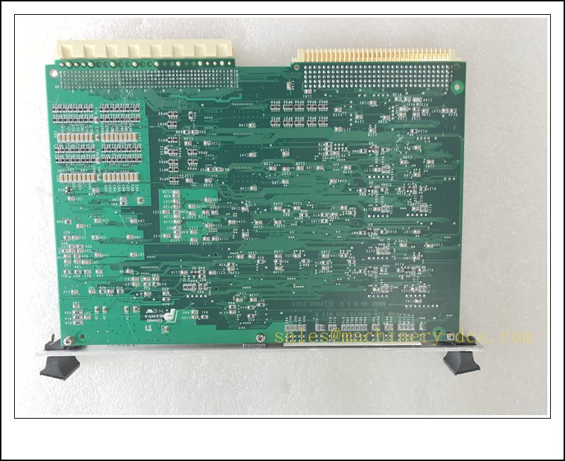
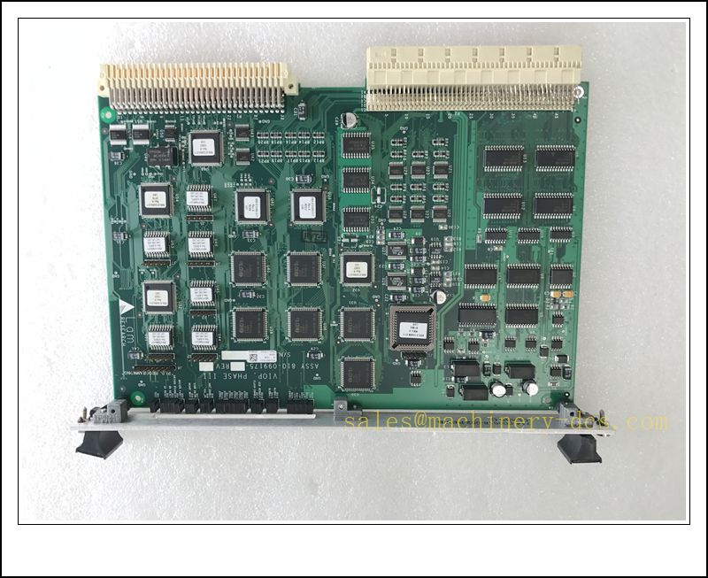
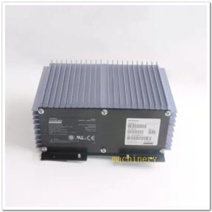
Lam Research 810-099175-011 | Phase III VIOP VME Bus Control PCB Board
Product Description
810-099175-011 is a VMEbus multi-layer control PCB board, also known as Phase III / VIOP board, designed exclusively for Lam Research wafer etch and thin-film processing semiconductor tools. It delivers high-speed I/O sequencing, analog signal conditioning, interlock logic and equipment state control for wafer process chambers. This board handles real-time chamber monitoring, gas valve interlock, sensor sampling and communication with the main tool CPU over VME backplane. It is built to withstand the strict EMI, temperature and chemical ambient environment inside semiconductor fab process bays, with on-board watchdog timer and fault latching protection for critical process safety interlocks. It is a proprietary OEM board, not a general-purpose industrial PLC module.
MTL810-099175-011
Technical Specifications
| Item | Parameter |
|---|---|
| Part Number | 810-099175-011 |
| Manufacturer | Lam Research |
| Board Type | VMEbus Control Board (Phase III VIOP) |
| Bus Interface | VME 32-bit backplane |
| Form Factor | Single-height VME card |
| Input Power | +5V, ±12V DC from VME backplane |
| Onboard Features | Watchdog timer, hardware interlock latches, multi-channel analog & digital signal conditioning |
| Operating Temperature | 0℃ ~ +60℃ (inside equipment cabinet) |
| Storage Temperature | -40℃ ~ +85℃ |
| Humidity | 10~90% RH non-condensing |
| PCB Construction | Multi-layer PCB, ESD protected circuitry |
| Communication | VME backplane, dedicated serial link to chamber sub-assemblies |
| Dimension | 233 × 160 mm (standard single height VME) |
| Weight | Approx. 0.32 kg |
| Application | Lam semiconductor wafer etch / deposition chamber control |
Compatibility & Installation Pitfalls
Compatibility
- Equipment Platform: Lam Research Phase III etch systems, matched VIOP chassis & VME rack
- Backplane: Standard VME backplane matching Lam tool rack; pin assignment is OEM customized, not generic VME
- Firmware: Factory pre-programmed onboard firmware. Firmware revision must match tool recipe & chamber configuration
- Replacement: Must use same revision level board; different hardware revisions are not drop-in compatible
Critical Installation Pitfalls
- Proprietary OEM hardware: This board is dedicated Lam tool part. It cannot be used in standard industrial VME PLC systems.
- Revision mismatch: Hardware revision is critical. Even same part number with different rev code may cause recipe abort or interlock failure.
- Extreme ESD sensitivity: Semiconductor PCB with fine feature components. ESD wristband and ESD mat mandatory. Touch only card edge handles; never touch components or connector pins.
- Hot insertion forbidden: Never insert/remove VME board with rack powered. Hot plug will permanently damage VME bus drivers and onboard ASICs.
- Fab chemical residue risk: When removing old board, residual process vapors/chemical contamination may be present; follow fab lockout/tagout and decontamination procedure.
- VME backplane pin damage: Bent backplane pins will cause intermittent VME communication crash, random chamber fault trips.
- Firmware & recipe binding: After board swap, tool chamber recipe, interlock map and calibration parameters need reloading. Skipping calibration leads to wafer scrap risk.
- Cooling airflow: Board relies on tool internal forced air cooling. Blocked fan or dust buildup causes thermal shutdown during wafer run.
Standard Operating Procedure (SOP)
1. Pre-Installation Inspection & LOTO
- Verify part number 810-099175-011 and hardware revision. Inspect PCB for scratches, burnt components, bent VME edge connector.
- Execute equipment lockout / tagout, purge chamber, confirm hazardous gas & RF power are fully disabled per fab safety procedure.
- Prepare ESD workstation, ESD wrist strap, anti-static bag, Lam tool service software, recipe backup and revision documentation.
2. Mechanical Removal & Mounting
- Open VME card cage door, release board retention latch. Extract old board by pulling card handles only.
- Place faulty board into ESD anti-static bag immediately.
- Unpack new replacement board only on ESD mat. Align board with VME guide rails, insert smoothly into slot.
- Lock retention latch firmly, ensure full seating into VME backplane.
3. Pre-Power Check
- Visually double check full insertion, no bent pins. Confirm slot assignment matches original slot location.
- Inspect nearby cables and connectors for interference. Confirm cabinet cooling fan is functional.
4. Power-Up & Commissioning
- Restore equipment power, boot tool controller.
- Launch Lam service software, read board identity and firmware revision.
- Reload chamber interlock configuration, calibration parameters and recipe settings.
- Perform hardware interlock simulation test, verify all digital & analog sensor channels.
- Run dry chamber test, check watchdog and fault latch functions.
- Execute qualification wafer test to confirm stable process before production release.
5. Maintenance & Replacement
- Periodic inspection: Dust cleaning, fan airflow check, board temperature monitoring.
- Fault troubleshooting: Read VME bus error logs and chamber interlock fault codes from tool HMI.
- Replacement: Repeat LOTO + ESD control, swap board, reload config and perform full chamber qualification.
Application Scenarios
- Lam Research Phase III semiconductor wafer etch chamber control
- Plasma etch process gas valve interlock and sensor signal acquisition
- Wafer processing chamber safety interlock & watchdog protection
- Real-time analog sampling of chamber pressure, temperature and gas flow transducers
- Semiconductor fab front-end wafer manufacturing process equipment control
Supporting / Matching Components
- Lam Research Phase III VME card cage & customized VME backplane
- Matching VME power supply module for Lam tool rack
- Chamber pressure / temperature / flow field sensors
- Gas solenoid valve drive sub-assemblies
- Tool host CPU main VME processor board
- Lam proprietary service & diagnostic software
- ESD workstation, anti-static bags, ESD wrist strap
- Chamber interlock terminal wiring harness
- Tool cooling fan assembly
- RF generator and chamber process sub-system
15 Recommended Same-Series / Compatible Lam Models
- 810-099175-012 – Updated VIOP board variant
- 810-099175-103 – Phase III revised VIOP PCB
- 810-099175-001 – Early revision VIOP board
- 810-099175-005 – Alternate chamber I/O variant
- 714-A22749-002 – Lam RF filter board
- 0041-51865 – RF power filter module
- 0041-50817 – RF matching network board
- 810-001844-001 – VME CPU board for Phase III rack
- 810-010430-001 – Analog measurement daughter board
- 810-020112-001 – Digital output interlock board
- 810-098765-001 – Chamber temperature monitor PCB
- 810-087654-002 – Gas flow control interface board
- 715-001234-001 – VME backplane for Phase III rack
- 0190-023456-001 – Chamber relay driver board
- 810-099176-011 – Next generation VIOP replacement board
FAQ
- Q: Is 810-099175-011 compatible with standard generic VME systems? A: No. It is Lam proprietary OEM board with custom pinout and firmware, only works inside matching Lam Phase III etch tool.
- Q: Can I hot-swap this VME board? A: No. Power must be fully locked out before board removal, hot swap will damage VME bus and PCB components.
- Q: Can I directly install different hardware revision as drop-in replacement? A: Not recommended. Revision mismatch may cause interlock trip, recipe failure and wafer scrap. Must match original revision and reload calibration.
- Q: Why the name confused with MTL? A: MTL is Eaton MTL for hazardous-area I/O. 810-099175-011 is Lam semiconductor board; “MTL810” is likely typo.

 Send an Email