
Description
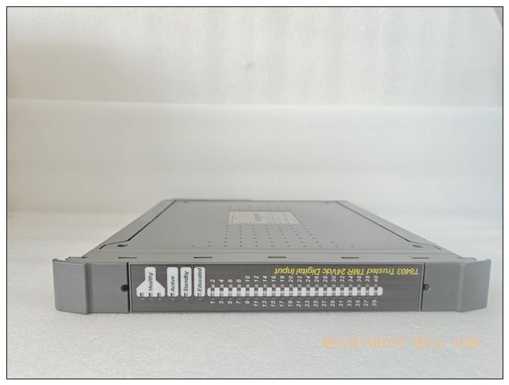
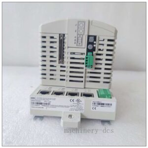
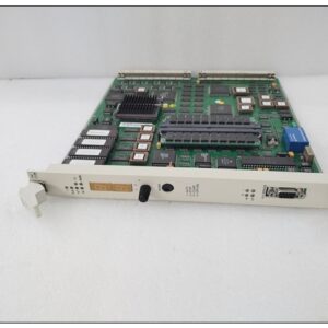
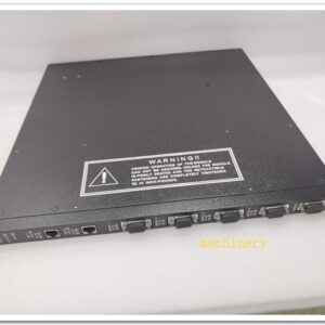
ICS TRIPLEX T8403 TMR 24 VDC Digital Input Module
Official Product Title: ICS TRIPLEX T8403 TMR 24 VDC Digital Input Module
Brand: ICS TRIPLEX (Rockwell Automation)
Model: T8403
Product Series: Trusted T8000 SIS Safety Instrumented System Series
Country of Origin: United Kingdom
Product Type: Rack‑mount TMR Safety Digital Input Module
Product Core Overview
The ICS TRIPLEX T8403 is a high‑integrity Triple‑Modular‑Redundant (TMR) digital input module designed for Trusted safety‑instrumented systems (SIS). It acquires 24 VDC dry‑contact and active digital signals from field switches, pressure‑limit switches, safety valves and emergency trip devicesCSDN博….
Adopting 2‑out‑of‑three voting logic, the module eliminates single‑point‑of‑failure risks; even one internal signal path fails, valid field status can still be guaranteed for safety interlock calculation. It supports 1 ms resolution Sequence‑of‑Event (SOE) logging, channel‑level open‑circuit / short‑circuit line diagnostics and 2500 V galvanic isolation per channelCSDN博…. TÜV‑certified for IEC 61508 SIL 3 safety integrity level. It is widely deployed for ESD emergency shutdown, BMS burner management, fire‑gas protection in petrochemical, power and offshore industries, supporting new‑project deployment and legacy Trusted system spare‑part retrofitting.
T8403
Main Technical Specifications
| Parameter | Specification |
|---|---|
| Manufacturer | ICS TRIPLEX (Rockwell Automation) |
| Model | T8403 |
| Module Type | TMR Safety Digital Input Module |
| Input Channels | 40‑channel 24 VDC digital input |
| Signal Type | Dry‑contact, NPN / PNP active 24 VDC signal |
| Safety Certification | TÜV IEC 61508 SIL 3 |
| Isolation | 2500 V galvanic isolation per channel |
| SOE Timestamp Resolution | 1 ms |
| Diagnostic Function | Channel open‑circuit / short‑circuit line monitoring |
| Power Supply | Powered by Trusted rack backplane |
| Operating Temperature | ‑20 ℃ ~ +60 ℃ |
| Storage Temperature | ‑40 ℃ ~ +85 ℃ |
| Humidity | 5 %‑95 % non‑condensing |
| Mounting | Standard Trusted rack slot‑mount, hot‑swappable |
| Compatibility | Trusted T8100 / T8110B / T8300 series controller racks |
| Certification | CE, UL, ATEX Zone 2 / Division 2 compliant |
| Weight | 1.2 kg |
| Warranty | 12‑month manufacturer warranty |
Trusted T8000 Series Recommended Models (6+)
- T8403: 40‑channel TMR 24 VDC digital input module (reference main model)
- T8431: TMR digital output module, relay contact output for safety solenoid actuation
- T8451: Analog input module, 8‑channel 4‑20 mA for safety‑related process signal acquisition
- T8461: Analog output module, TMR 4‑20 mA output for safety valve position control
- T8110B: Trusted main CPU processor module, TMR safety controller core unit
- T8800: Communication interface module, Modbus‑TCP / Modbus‑RTU gateway for DCS connection
- T8423: High‑safety digital input module with enhanced intrinsic‑safety barrier compatibility
Professional Quality Control & Test Standard Operating Procedure (SOP)
- Incoming Component Inspection Inspect TMR signal‑processing chips, isolation optocouplers, backplane connectors and PCB substrates. Verify all components comply with ICS TRIPLEX safety‑grade component specifications. Reject non‑conforming parts prior to assembly.
- PCB Assembly & Channel‑by‑Channel Bench Test After SMT assembly, perform power‑on initialization. Inject simulated 24 VDC on‑off signals for every channel. Validate three‑path TMR signal acquisition, 2‑out‑of‑3 voting function, line‑fault detection and SOE timestamp accuracy.
- Thermal Burn‑in Aging Test 72‑hour continuous powered aging at 55 ℃ ambient temperature. Run cyclic safety‑signal simulation. Monitor channel drift, backplane communication stability and temperature rise, screen early‑failure hardware defects.
- Environmental Compliance Validation Execute temperature cycling, mechanical vibration‑shock and EMC EMI/EMS testing according to IEC 61000‑6‑2 and IEC 60068 standards. Verify performance under industrial harsh‑interference simulation for safety‑system hardware.
- Full‑System Trusted Rack Integration Test Insert into standard Trusted rack. Test backplane TMR bus interaction with CPU and other I/O modules. Verify fault reporting, SOE event logging, hot‑swap behaviour and TriStation 1131 software online diagnosis function.
- Final Calibration & Batch Sampling Release Calibrate input threshold and diagnostic parameters. Perform 5 % random‑sample retest for each production batch. Generate traceable safety‑system factory‑test reports before labelling and shipment.
T8403
New Module Installation Guidelines
6.1 Pre‑installation Preparation
Power‑off the target Trusted rack, or confirm redundant system permits hot‑swap maintenance. Wear anti‑static wristband for ESD protection. Inspect for shell damage, bent backplane pins or connector corrosion. Prepare shielded field signal cables and insulated screwdrivers.
6.2 Hardware Rack Installation
Slide horizontally into the designated I/O slot of Trusted rack. Push firmly until backplane connector is fully seated. Fasten front‑panel locking screws. Route field 24 VDC signal cables separately; keep signal wiring away from high‑power AC cables to reduce electromagnetic interference. Terminate cable shielding strictly per official wiring diagram.
6.3 System Configuration & Commissioning
Restore rack power supply. Launch TriStation 1131 engineering software. Recognize the newly installed module over TMR backplane bus. Configure channel input mode, line‑diagnosis enable/disable, SOE logging parameters and safety‑logic mapping. Inject simulated field signals to verify voting logic, fault alarm and SOE timestamp recording. Save complete project configuration files for offline backup.
6.4 Post‑installation Validation
Check front‑panel LED status indicators (RUN, FAULT, CHANNEL DIAG). Verify real‑time digital‑input status and event‑log records. Perform continuous 4‑hour runtime test. Confirm no false faults, signal dropout or communication exceptions, complete commissioning acceptance.
Application Scenarios & Product Features
Application Scenarios
- Petrochemical & refinery ESD emergency shutdown safety‑instrumented systems
- Power‑plant BMS burner management, turbine safety interlock protection
- Off‑shore oil‑gas platform fire‑gas (F&G) safety monitoring systems
- Chemical plant reactor safety interlock and hazardous‑process protection
- Legacy ICS TRIPLEX Trusted system spare‑part replacement & system retrofitting
- Hazardous‑area Zone 2 / Division 2 safety‑related discrete‑signal acquisition
Core Features
- Triple‑Modular‑Redundant (TMR) architecture with 2‑out‑of‑3 voting, eliminates single‑point‑of‑failure
- 40‑channel high‑density 24 VDC digital input for large‑scale safety‑signal collection
- TÜV‑certified IEC 61508 SIL 3 safety integrity for safety‑instrumented‑system applications
- Per‑channel 2500 V galvanic isolation, improving anti‑interference performance for field loops
- Built‑in channel‑level open‑circuit / short‑circuit line fault diagnosis
- 1 ms high‑precision SOE sequence‑of‑event logging for post‑trip root‑cause analysis
- Hot‑swap support, minimize system downtime during module replacement
- Full interoperability with Trusted series CPU and I/O modules via TMR backplane bus
- Conformal‑coated hardware option for high‑humidity, salt‑fog offshore environments
T8403
Frequently Asked Questions (FAQ)
Q1: Module FAULT LED illuminates immediately after rack power‑on
A1: Check rack backplane power supply status. Confirm is fully inserted and front‑panel screws locked. Review diagnostic logs in TriStation 1131 for detailed fault codes. Complete full‑system power‑cycle reset. If fault persists, return for hardware inspection.
Q2: Individual channel shows “field‑line fault” alarm
A2: Inspect field wiring for open‑circuit, short‑circuit or poor terminal contact. Verify actual field‑device matches configured signal type. Check 24 VDC field‑loop power status. Replace field cable for fault isolation.
Q3: Input signal status reads unstable, frequent status flicker
A3: Check cable‑shield grounding quality; separate signal cables from high‑voltage power cables. Confirm field‑loop voltage stays within rated 24 VDC range. Review channel‑input threshold configuration parameters. Eliminate on‑site electromagnetic interference sources.
Q4: Can work with older Trusted rack hardware revisions?
A4: Backward compatible with most Trusted racks. Very early hardware revisions require CPU firmware upgrade to achieve full TMR‑voting and SOE‑logging functions.
Q5: No SOE event records generated when field‑signal status changes
A5: Confirm SOE function is enabled in TriStation 1131 configuration. Verify system time synchronization for timestamp. Check whether related channels are assigned for SOE logging. Re‑download complete configuration to the rack.
Q6: What routine maintenance is required for safety‑grade module?
A6: Every 3‑6 months inspect cabinet ventilation and dust accumulation; check terminal‑screw tightness. Regularly back‑up TriStation project configuration files. Keep cabinet operating temperature within rated range. Do not clean circuit‑board assemblies with liquid solvents. Periodically review system diagnostic alarm logs.

 Start Chat


 Send an Email


