
Description
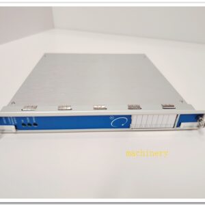
Honeywell FC‑BKM‑001 Battery and Key Switch Module
Title
Honeywell FC‑BKM‑001 Battery and Key Switch Module for FSC / Safety Manager SIS System
Meta‑Description
Honeywell FC‑BKM‑001 is a utility battery‑backup & key‑switch module for Honeywell FSC and Safety Manager SIS racks. It provides lithium‑battery SRAM memory backup for safety logic data retention during power loss, plus physical key‑lock switch to select Run / Program / Force modes, enforces hardware‑level access authorization for SIL3 safety‑instrumented systemselectronic….
FC‑BKM‑001
Product Core Overview
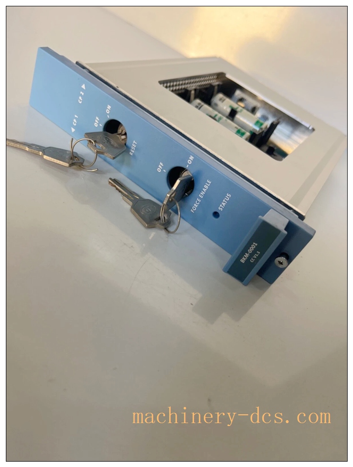
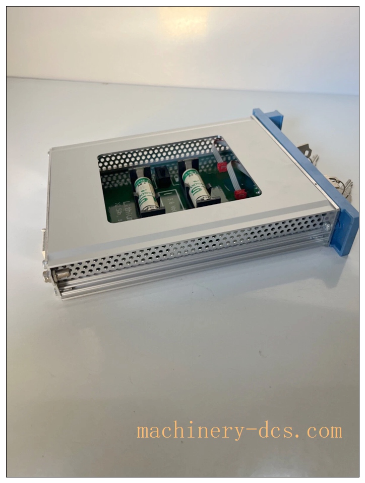
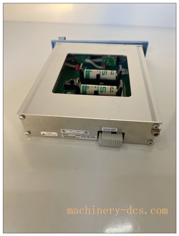
FC‑BKM‑001 is an essential utility rack module for Honeywell FSC / Safety Manager safety instrumented system. It integrates two core functions: lithium‑thionyl‑chloride battery memory backup and physical key‑operated mode switch.
The internal 3.6 V lithium battery backs up controller SRAM, preserving safety application logic, force values and diagnostic data when main rack power is lost. Without this module, volatile SRAM data will be cleared after power failure. The front‑panel key switch provides hardware‑enforced mode selection: RUN, PROGRAM, FORCE. Keys must be physically turned to enable programming or forcing functions; this prevents unauthorized online modification of safety logic, which is critical for SIS safety complianceelectronic….
Module plugs into FSC rack backplane, communicates via system safety bus, reports battery‑low diagnostic alarms to SIS controller. Widely used in petrochemical, oil‑gas SIL3 ESD‑interlock racks. Battery has limited service life and requires periodic replacement during system maintenance.
Main Technical Specifications
| Item | Parameter |
|---|---|
| Part Number | FC‑BKM‑001 |
| Module Type | Battery Backup & Key‑Switch Utility Module |
| Compatible System | Honeywell FSC / Safety Manager SIS rack |
| Internal Battery | 3.6 V Lithium‑thionyl chloride, 2 Ah (SAFT LS14500CFG or equivalent) |
| Typical Backup Time | Up to 10 hours for SRAM data retention |
| Key‑Switch Modes | RUN / PROGRAM / FORCE (hardware key‑lock) |
| Supply Voltage | 24 VDC (‑15% ~ +30%)electronic… |
| Supply Current | Typical 7 mA; Max 20 mAelectronic… |
| Diagnostics | Battery low‑voltage detection, module health fault reporting |
| LED Indicators | Module OK, Battery Low status LED |
| Safety Certification | TÜV SIL3, CE, UL/cULus, FM |
| Operating Temperature | −5 °C ~ +70 °C |
| Storage Temperature | −40 °C ~ +85 °C |
| Relative Humidity | 5 %‑95 % non‑condensing |
| Mounting | Standard FSC rack‑slot installation |
| Hot‑Swap | Mechanically hot‑swappable; observe SIS bypass procedure |
Quality Control Procedures
- Visual & Mechanical Incoming Inspection: Inspect PCB, front‑panel key‑lock mechanism, battery compartment, labeling and serial‑number marking. Serial‑number recorded for full‑lifecycle traceability.
- Backplane Interface Continuity Test: Verify pin continuity, insulation and isolation for FSC backplane connector.
- Battery‑Backup Functional Test: Validate SRAM data retention under simulated main‑power‑loss condition. Verify battery‑low threshold alarm triggers correctly.
- Key‑Switch Mode‑Logic Test: Toggle key through RUN / PROGRAM / FORCE positions; verify system correctly accepts or rejects programming/force operations matching hardware‑switch state.
- Safety‑bus Communication Test: Confirm reliable status reporting between FC‑BKM‑001 and SIS safety processor.
- Environmental Stress Screening: Temperature‑cycle test across operating temperature range.
- EMC Compatibility Test: Industrial electromagnetic‑interference test.
- Final End‑of‑Line Validation & Archiving: Full‑function test suite completed; test records archived linked to unit serial‑number before factory release.
Related Brand Model Recommendations
- FC‑SDIL‑160824VDC: 16‑channel loop‑monitored safety digital‑input module.
- FC‑SDO‑0824: 8‑channel safety solid‑state digital‑output module.
- Matching Controller: Honeywell Safety Manager / FSC safety processor unit.
- System Accessories: FSC rack carrier, spare replacement lithium‑battery cells, safety termination FTA assemblies.
Frequently Asked Questions (FAQ)
Q1: What happens if FC‑BKM‑001 battery drains completely? A: After main rack power loss, SRAM safety‑logic data, force values will be lost. Upon power‑restore, controller downloads project from non‑volatile flash memory, but active force‑override states are cleared. “Battery Low” alarm will be generated in advance before full depletion.
Q2: What is the function of the key‑switch? A: Hardware‑level access control. Key must be turned to PROGRAM to download project; FORCE position permits channel‑force‑override. In RUN position, online programming / forcing is blocked even if software login credentials are obtained, preventing unauthorized safety‑logic modificationelectronic….
Q3: Can I hot‑swap FC‑BKM‑001 on running SIS rack? A: Mechanically hot‑plug is possible. But for live safety rack, execute safety bypass procedure as per Honeywell manual before replacement. Short time without battery backup may lose SRAM volatile data during swap.
Q4: Does this module supply operating power for the SIS controller? A: No. It only provides small‑capacity power for SRAM memory backup. Main controller power still comes from rack power supply unit.
Q5: Can I replace battery on‑site? A: Battery compartment is accessible on module front‑face. Use Honeywell‑approved 3.6 V lithium‑thionyl‑chloride cell; strictly follow site SIS maintenance procedure. Improper battery model invalidates certification.
Q6: Can I repair module on‑site? A: No. Unauthorized disassembly voids SIL‑certification and warranty. Return defective unit to authorized service centre.
FC‑BKM‑001
Installation & Configuration Guide
Pre‑Installation
- Inspect module for transit damage. Confirm part‑number FC‑BKM‑001 and serial‑number match purchase‑order. Check battery status.
- Confirm FSC / Safety Manager rack, backplane and safety‑processor are functional.
- Review SIS operation manual for key‑switch operation rules and battery‑replacement maintenance requirements.
Mechanical Installation
- Insert FC‑BKM‑001 into designated FSC rack slot, push firmly until backplane‑connector fully mates. Tighten front‑panel captive fasteners.
Important: For replacement in running SIS rack, execute safety‑bypass procedure. Short‑term loss of battery backup will clear SRAM volatile data.
Electrical Wiring
- No external field‑signal wiring. Module communicates entirely via rack internal backplane bus.
- Ensure rack chassis proper grounding per site specification.
System Configuration & Commissioning
- After installation, power‑on rack. Observe front‑panel LED: OK LED shall be on; no Battery‑Low alarm.
- Connect Safety Builder configuration software to SIS controller. Verify system correctly reads module status, battery‑health information and key‑switch position.
- Test key‑switch function:
- Key in RUN: verify download / force operations are rejected.
- Key in PROGRAM: verify project download is permitted.
- Key in FORCE: verify channel‑force‑override function is available.
- Simulate main‑power‑off test (project‑specific approval required) to verify SRAM data retention with battery backup.
- Confirm battery‑low diagnostic alarm is reported correctly. Save full‑project configuration backup file, place system into normal SIS operation.

 Start Chat


 Send an Email


