
Description
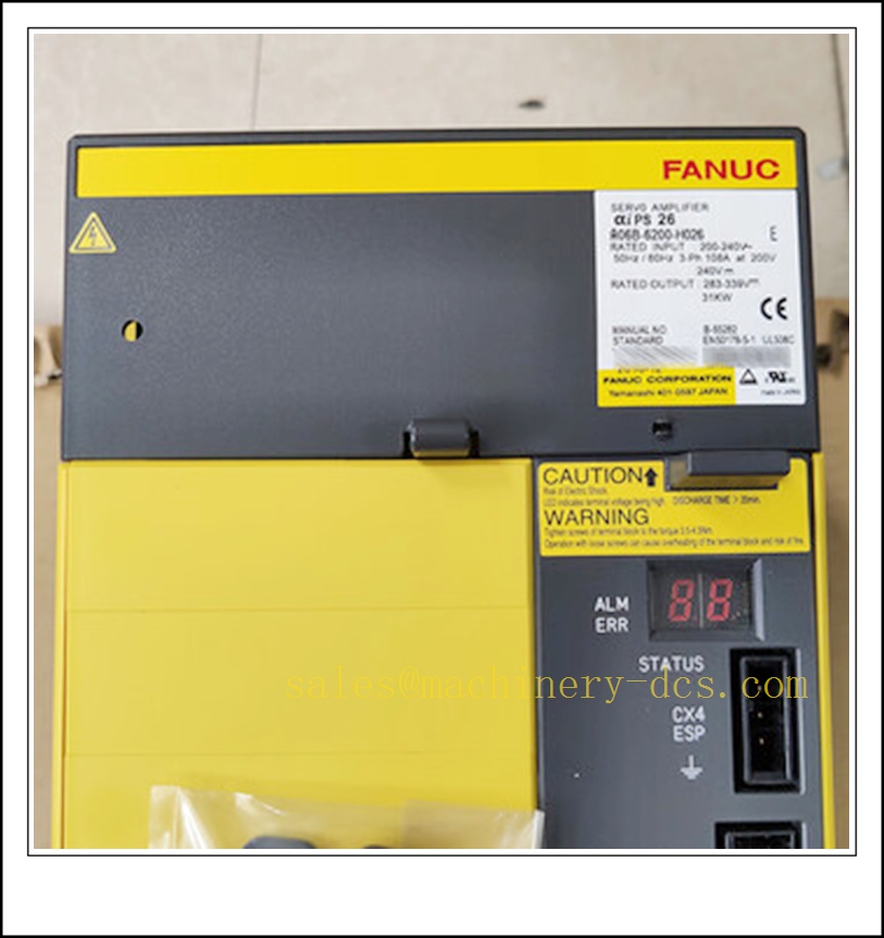
FANUC A06B-6200-H026 αiPS 26-B Power Supply Module for αi Series Servo and Spindle Amplifiers
Product Description
The A06B-6200-H026 is an αiPS 26-B power supply module of FANUC Alpha i-B series. It converts three-phase 200–240VAC industrial mains into regulated DC bus voltage for the whole drive group including αiSV servo amplifiers and αiSP spindle amplifiers. It integrates active regenerative circuit to feed back braking energy to the AC power grid, reducing heat generation and energy consumption. The module communicates with FANUC CNC or robot controller via dedicated fiber servo link, and delivers built-in multi-layer hardware protection functions. It cannot operate independently; it must work in conjunction with matched servo and spindle drive units within the same drive stack.
Technical Specifications
- Brand: FANUC
- Part Number: A06B-6200-H026
- Model: αiPS 26-B
- Product Type: Power Supply Module (PSM)
- Input: 3-phase AC 200–240V, 50/60 Hz, rated 108A at 200V
- DC Bus Output: 283 ~ 339 VDC, rated power 31kW
- Auxiliary Output: 24VDC control power
- Regeneration Mode: Active grid regeneration
- Communication: FANUC proprietary optical fiber servo link
- Cooling: Forced air cooling, internal fan A90L-0001-0581
- Protection: Overcurrent, overvoltage, undervoltage, overload, pre-charge fault, fan failure, overheat
- Operating Temperature: 0 °C ~ +55 °C
- Storage Temperature: -20 °C ~ +70 °C
- Relative Humidity: 5% ~ 95%, non-condensing
- Mounting: Vertical cabinet rack mounting
- Certification: CE, UL, KCC
- Approximate Weight: 9.2 kg
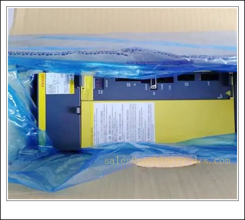
A06B-6200-H026
Application Scenarios
- High-power FANUC 0i-MF / 30i-B CNC machining centers and vertical milling machines
- Heavy-duty CNC lathes with multiple servo axes and high-torque spindle
- FANUC R-30iB / R-30iB Plus robot systems with high-load external 7th/8th axes
- Gantry machine tools and large automated transfer lines with multi-axis synchronized motion
- Automotive production welding and handling robot auxiliary positioner drive stacks
- Aerospace heavy-cutting CNC equipment with high regenerative load
- Machine tool retrofit and upgrade of existing Alpha i-B drive groups
- Spare replacement and maintenance for FANUC αiPS 26-B power units
8 Related FANUC Model Recommendations
- A06B-6200-H011 – αiPS 11-B Power Supply Module
- A06B-6200-H030 – αiPS 30-B Power Supply Module
- A06B-6240-H209 – αiSV 80/80-B Dual Axis Servo Amplifier
- A06B-6220-H026 – αiSP 26-B Spindle Amplifier
- A06B-0265-B605 – αiS Servo Motor
- A06B-0238-B605 – αiS Spindle Motor
- A02B-0338-B502 – 31i-B CNC Main Unit
- A06B-6240-H207 – αiSV 60/60-B Dual Axis Servo Amplifier
Compatibility & Installation Pitfalls
Compatibility
- Designed for FANUC αi-B series drives; paired with αiSV servo and αiSP spindle amplifiers. Not compatible with older αi-A series drives without hardware and firmware matching.
- Matched for FANUC 0i-MF, 30i-B CNC and R-30iB / R-30iB Plus robot controllers.
- It only provides DC bus power; it cannot drive motors by itself.
- Must use FANUC specified fiber cables for servo link; generic fiber will trigger communication alarms.
- The total power consumption of all connected servo and spindle amplifiers must not exceed the 31kW rated capacity of this power supply.
- CNC/robot controller firmware must support αiPS 26-B; mismatched firmware causes link failure.
Installation Pitfalls
- High-voltage DC bus capacitors retain dangerous charge long after AC power is cut off. Follow discharge procedure and wait sufficient time before touching terminals.
- Three-phase AC input phase sequence must be correct; wrong phase sequence will trigger power supply alarm immediately.
- Install vertically and keep upper and lower ventilation space unblocked. Dust accumulation or blocked air duct will lead to overheat alarm.
- Power cables and fiber communication cables shall be routed separately. Cable shielding must be grounded at cabinet side to suppress EMI.
- Do not hot-plug fiber connectors, main AC terminals or DC bus connectors under energized status.
- The cooling fan is a consumable spare part. Replace the fan promptly once abnormal noise or stall alarm appears. Continuous operation without cooling will damage the power module.
- When multiple drives share one αiPS power supply, check the total peak current of all axes to avoid overload during simultaneous acceleration.
- Do not modify the regeneration circuit; active regeneration units are factory-tuned and improper modification can feed surge back to plant mains.
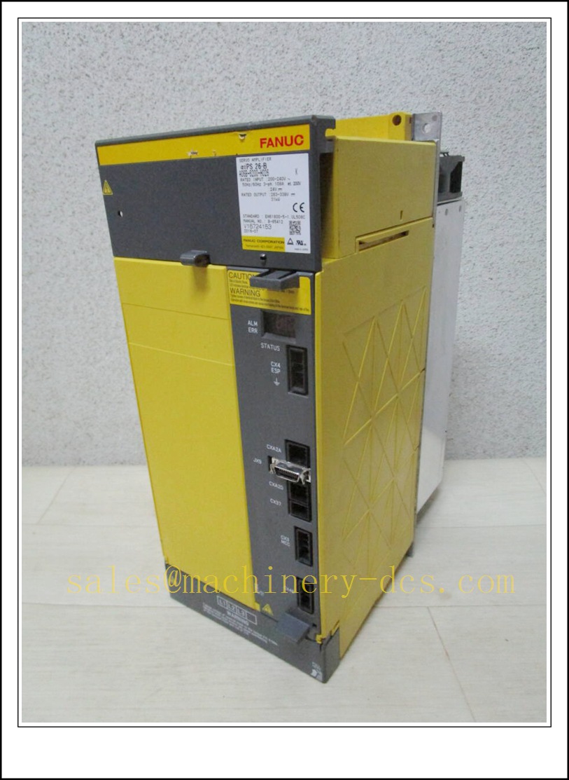
A06B-6200-H026
Standard Operating Procedure (SOP)
SOP for A06B-6200-H026 Power Supply Module Inspection, Installation and Functional Test
- Pre-Installation Inspection Check the module for casing deformation, burnt marks, bent terminals or contamination. Confirm part number A06B-6200-H026. Verify compatibility with CNC/robot firmware and the total power rating of downstream servo/spindle amplifiers. Review the main AC wiring diagram, DC bus layout and emergency stop circuit. Apply lockout-tagout to the incoming three-phase power.
- Rack Installation Mount the power supply vertically inside the electrical cabinet and fasten mounting screws. Wire three-phase AC input terminals, DC bus output terminals and 24V control power. Connect optical fiber servo links between the power supply, servo amplifiers and CNC/robot controller. Separate high-power wiring from signal cables and implement EMC grounding as per FANUC specification.
- Configuration and Parameter Setup Power on the controller with all motor loads disconnected. Confirm fiber link handshake is established normally. Load the machine parameter file, set axis assignment and spindle parameters. Save parameter backup to CNC memory or external storage. Clear all power-supply related alarms before applying mechanical load.
- Power Unit and Regeneration Test Energize the drive stack under no-load status. Check LED status codes of the αiPS module. Execute JOG test for servo axes and spindle rotation. Simulate rapid deceleration to verify regeneration function works correctly. Record alarm responses for overvoltage, overload and fan fault in the maintenance log.
- Load Commissioning Couple all servo and spindle loads to machinery. Run low-speed test cycles, then gradually increase speed and acceleration to rated operating range. Observe DC bus fluctuation during acceleration and deceleration. Confirm regeneration circuit absorbs braking energy normally without overvoltage alarms. Ensure faults only generate diagnostic alerts and do not cause uncontrolled axis movement.
- Return to Production Service Reset alarm latches and acknowledge diagnostic messages. Remove lockout-tagout. Monitor input current, DC bus voltage and module temperature through the observation period. Notify production that the αiPS power supply module is commissioned and ready for operation.
- Periodic Maintenance and Replacement During scheduled downtime, inspect fan rotation, terminal torque, cable insulation and capacitor health. Perform overload and regeneration proof-test according to machine maintenance schedule. If the power supply reports persistent unrecoverable faults, lock out main power before replacement. After replacement, reload parameters, re-establish fiber link and complete full no-load and loaded cycle test before releasing the machine to production.

 Start Chat


 Send an Email


