
Description
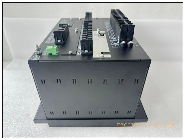
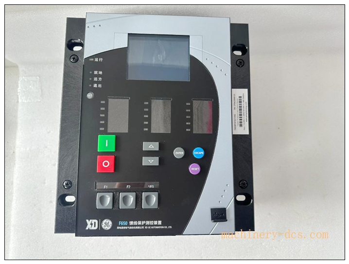
F650 Numerical Feeder Protection & Bay Controller, Order‑code F650NFLF2G5HIP6E
Brand: GE Vernova (Former GE Multilin)
Model: F650NFLF2G5HIP6E
Product Series: F650 Modular Bay‑controller IED
Country of Origin: Canada / USA
Product Type: Panel‑mount numerical feeder protection, control & metering IED
Status: Active legacy product; spare‑parts & new‑build supply available
Order‑code Decode F650‑N‑F‑L‑F‑2‑G‑5‑H‑I‑P‑6‑E
- N: Base CPU platform
- F: 3‑phase current 5A + neutral current input
- L: 3‑phase voltage + auxiliary voltage input
- F: Feeder base protection function set
- 2: Power supply: 110‑250 VDC / 120‑230 VAC wide‑range
- G: Graphical LCD HMI with keypad & status LEDs, single‑line diagram support
- 5: Slot‑5 I/O board: 8DI +8DO
- H: Slot‑6 I/O board: 8DI +8DO
- I: Slot‑7 I/O board: 8DI +8DO
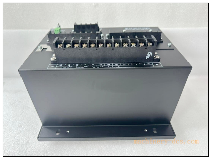
- P: Rear communication: Ethernet RJ45 + RS485/RS232 serial
- 6: Advanced protocol suite: IEC 61850 Ed2, Modbus‑TCP/RTU, DNP3.0, IEC‑60870‑5‑103/104
- E: Conformal coated (harsh‑environment tropical coating)
Total I/O count for this order: 24 Digital Inputs, 24 Digital Outputs
F650NFLF2G5HIP6E
Product Core Overview
F650NFLF2G5HIP6E is a high‑performance modular numerical IED for medium‑voltage feeder bay protection, control, metering and automation. Built‑in DSP high‑speed sampling (64 samples/cycle) delivers feeder‑oriented protection library, breaker control, auto‑reclosing, fault‑location, disturbance oscillography, event sequence recording, programmable bay interlocking logic (IEC 61131‑3). Equipped with 3 sets I/O boards, graphical local HMI, multi‑port communication and harsh‑environment conformal coating. Widely deployed in power‑utility substations, industrial MV switchgear, petrochemical, mining, renewable‑energy switch‑yard bay control applicationsGE Vernova.
Main Technical Specifications
| Parameter | Specification |
|---|---|
| Manufacturer | GE Vernova Multilin |
| Model | F650NFLF2G5HIP6E |
| Auxiliary Power | 110‑250 VDC / 120‑230 VAC (code‑2) |
| CT Input | 5 A rated (1 A optional via setting); 3‑phase + neutral |
| VT Input | 3‑phase voltage + auxiliary‑neutral voltage input |
| Digital Inputs | 24 opto‑isolated DI (20‑230 Vdc threshold) |
| Digital Outputs | 24 Form‑C relay outputs; trip‑circuit supervision supported |
| HMI | Graphical LCD, configurable single‑line diagram, function keypad, status LEDs |
| Rear Communication | 10/100 Ethernet RJ45; RS485 / RS232 serial port |
| Supported Protocols | IEC 61850 Ed2, Modbus‑TCP/RTU, DNP3.0, IEC‑60870‑5‑103/104; PRP/HSR; RSTP; SNTP / IRIG‑B / IEEE1588 PTP time sync |
| Protection Functions | Phase/Ground time‑overcurrent 51/51N; instantaneous 50/50N; directional overcurrent 67/67N; sensitive earth fault; over‑/under‑voltage 59/27; over‑/under‑frequency 81O/81U; breaker‑failure; auto‑reclosing‑79; fault‑location; negative‑sequence unbalance; load‑shedding logic |
| Recording | Event‑sequence log (1023 events); multi‑channel oscillography; data‑logger; fault‑location report; self‑supervision alarm logManualsLib |
| Logic Engine | IEC 61131‑3 programmable logic for bay‑interlock, breaker‑control |
| Mounting | Flush panel‑mount / 19‑inch half‑rack mounting |
| Dimension | 266 mm(H) ×144 mm(W) ×280 mm(D) |
| Weight | approx 4.2 kg |
| Front‑face rating | IP54; rear terminals IP20 |
| Operating Temperature | −20 ℃ ~ +60 ℃; conformal coated for humid / corrosive environment (‑E suffix) |
| Storage Temperature | −40 ℃ ~ +85 ℃ |
| Humidity | 5‑95 % RH non‑condensing |
| Certifications | CE, KEMA IEC61850‑Ed2 certified, IEC60255, UL |
| Configuration Software | EnerVista 650 Setup tool |
| Warranty | 12‑month |
F650 series related models
- F650NFLF2G5HIP6E: Reference unit, full‑I/O 24DI+24DO, conformal coated, full‑protocol suite
- F650NFLF2G0L0P6: Base‑model, minimal I/O, no conformal coating
- F650‑CIO‑xx: CAN‑bus remote I/O extension modules for F650 bay‑controller
- F350: Compact‑class feeder‑protection IED (cost‑optimized alternative)
- EnerVista 650 Setup: Official configuration & monitoring software for family
Professional Quality Control & Test Standard Operating Procedure (SOP)
- Incoming Component Inspection Inspect CPU main‑board, CT/VT measuring modules, three I/O boards, power‑supply unit, communication board, HMI panel and rear terminal blocks. Verify components comply with GE‑Multilin protection‑grade specifications; reject non‑conforming components.
- PCB & Assembly Bench Functional Test After assembly, perform power‑on self‑test. Inject CT/VT analogue test signals to verify protection‑element pickup value & timing accuracy. Test all 24 DI & 24 DO channels, local graphical‑HMI display, single‑line‑diagram rendering, event‑logging and oscillography storage. Validate serial‑port and Ethernet multi‑protocol communication.
- Thermal Burn‑in Aging Test 72‑hour powered burn‑in test at 55 ℃ ambient. Run cyclic protection‑element simulation, continuous Ethernet & serial‑port polling, frequent I/O toggling. Monitor measuring‑channel thermal‑drift and communication stability to screen early‑life hardware defects.
- Environmental Compliance Validation Temperature cycling, vibration‑shock and EMC EMI/EMS testing comply with IEC 60255‑series standards for substation cabinet environment. Conformal‑coating quality inspection for “‑E” harsh‑environment variant.
- Full‑system integration test Connect with protection test‑set and SCADA host simulator. Verify IEC 61850 MMS/GOOSE, DNP3, Modbus‑TCP/RTU data exchange; IRIG‑B / PTP time‑synchronization; EnerVista 650 upload‑download settings; breaker‑control logic, auto‑reclosing sequence, fault‑location calculation and oscillography file export.
- Final calibration & batch‑sampling release Calibrate analogue‑measurement offset & protection‑element timing. 5 % random‑sample retest per batch. Record serial‑number, hardware‑revision and firmware‑version. Generate traceable factory‑test‑reports before labelling and shipment.
F650NFLF2G5HIP6E
Installation Guidelines
Safety note: This IED connects to high‑voltage CT/VT secondary circuits. Short‑circuit CT secondary before installation/maintenance to avoid hazardous open‑circuit voltage.
6.1 Pre‑installation Preparation
Switch‑off auxiliary power supply. Wear anti‑static wristband for ESD‑protection. Verify full order‑code F650NFLF2G5HIP6E, confirm 3‑pcs I/O boards fitted and conformal‑coated hardware‑revision matches requirement. Inspect mechanical damage, terminal‑pin deformation. Prepare EnerVista 650 Setup software, CT/VT wiring drawing, shielded Ethernet & serial communication cables.
6.2 Hardware Panel‑mount Installation
Install IED into cabinet panel cut‑out; secure mounting fixtures. Wire auxiliary AC/DC power‑supply, CT/VT secondary circuits, field binary‑input signals, relay‑output trip‑&‑control wiring strictly follow GE official drawings. Route signal cables separate from high‑power AC cables. Properly terminate cable shielding. Ensure CT secondary reliably short‑circuited before energizing primary equipment.
6.3 System Configuration & Commissioning
Power‑on IED. Connect PC via Ethernet or front‑RS232 port, launch EnerVista 650 Setup. Download application setting‑group: feeder rated‑parameters, protection thresholds, auto‑reclosing sequences, IEC‑61131‑3 bay‑interlock‑logic, DI/DO assignment, multi‑protocol communication parameters and time‑synchronization mode. Perform protection‑element simulation test, verify pickup‑value, operating‑time, relay‑trip‑action and breaker‑control sequence. Confirm event‑log, oscillography and fault‑location function. Save complete setting‑file for offline‑backup.
6.4 Post‑installation Validation
Check front‑panel HMI status and LED indicators. Verify measured values (phase‑current, phase‑voltage, frequency, power‑factor). Test communication data consistency with upper‑level SCADA system. Simulate fault‑conditions to validate protection‑trip and recording‑function. Run continuous 4‑hour runtime test. Confirm no self‑supervision faults, no false‑protection‑operation, complete commissioning‑acceptance.
Application Scenarios & Product Features
Application Scenarios
‑ Utility‑substation medium‑voltage feeder protection & bay‑control ‑ Industrial‑plant / petrochemical / mining MV switchgear feeder bay control ‑ Renewable‑energy (solar / wind) switch‑yard feeder protection ‑ Retrofit‑projects for existing GE‑Multilin ‑series installations requiring large‑I/O and harsh‑environment conformal‑coating
Core Features
‑ Comprehensive feeder‑oriented protection‑function library for phase‑fault, earth‑fault, directional‑fault, voltage‑frequency‑abnormality ‑ 24DI + 24DO full‑I/O configuration (3 I/O boards installed), rich hardware resources for complex bay‑interlocking and breaker‑control ‑ Harsh‑environment conformal‑coating (‑E suffix) for humid, corrosive substation / coastal environment ‑ Graphical local‑HMI with configurable single‑line‑diagram for on‑site operation & monitoring ‑ IEC 61131‑3 programmable logic engine for custom bay‑interlock logic ‑ Multi‑protocol communication suite: IEC 61850 Ed2 (GOOSE/MMS), Modbus‑TCP/RTU, DNP3.0, IEC‑103/104; support PRP/HSR redundant‑Ethernet; multiple time‑sync options (IRIG‑B / SNTP / IEEE1588‑PTP) ‑ Built‑in fault‑location calculation, disturbance‑oscillography, sequence‑of‑event recording, self‑supervision alarm ‑ Draw‑out modular hardware; individual I/O‑board replaceable without whole‑unit replacement ‑ Full‑function configuration & monitoring via EnerVista 650 Setup tool
Frequently Asked Questions (FAQ)
Q1: Self‑supervision fault alarm after power‑on
A1: Check auxiliary‑supply voltage within rated range. Read detailed fault‑code on local‑HMI or EnerVista software. Verify firmware‑hardware compatibility. Perform full power‑cycle reset. If alarm persists return unit for hardware inspection.
Q2: Protection mis‑operation or refuse‑to‑operate during secondary‑injection test
A2: Check CT/VT wiring polarity and connection integrity. Verify setting‑group parameters match actual feeder‑rated‑values. Confirm CT rated‑5A setting matches hardware. Re‑calibrate analogue‑measurement channels in EnerVista 650 Setup.
Q3: Cannot establish IEC‑61850 communication with station‑SCADA
A3: Verify Ethernet IP‑address, subnet‑mask, gateway configuration. Confirm SCL‑CID file imported correctly into IED; check GOOSE/MMS access‑control setting. Verify network‑switch supports IEC‑61850 traffic. Review IED communication‑diagnostic counters.
Q4: Can I swap individual I/O boards without downloading new settings?
A4: Same‑type replacement I/O‑board can be hot‑swapped (draw‑out unit). However, verify slot‑mapping in configuration; if board‑type changed, re‑configure and download setting‑file is mandatory.
Q5: What routine maintenance is required for ?
A5: Every 6‑12 months inspect cabinet ventilation and dust‑accumulation; check terminal‑screw tightness and Ethernet connector contact. Backup complete setting‑file. Periodically review self‑supervision‑alarm‑log and event‑history. Avoid long‑term cabinet over‑temperature operation. Do not clean circuit‑boards by liquid solvent.

 Start Chat


 Send an Email


