
Description
Eaton MTL8507-BI-DP | PAC8000 PROFIBUS-DP Bus Interface Module (BIM)
Product Description
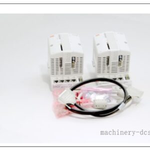
MTL8507-BI-DP is a Bus Interface Module (BIM) for Eaton MTL PAC8000 distributed I/O system, acting as the bridge between PAC8000 local I/O rack and PROFIBUS-DP master controller. It operates as a PROFIBUS-DP slave, collecting cyclic input/output data from up to 24 local PAC8000 I/O modules and exchanging process data with the DP host. This BIM supports HART pass-through for remote configuration and diagnostics of field HART transmitters, extended PROFIBUS diagnostics, non-volatile configuration storage, and redundant deployment on dedicated carrier for high availability. Galvanic isolation is implemented between PROFIBUS-DP bus and I/O backplane to suppress ground loop noise, designed for hazardous and heavy EMI process industries.
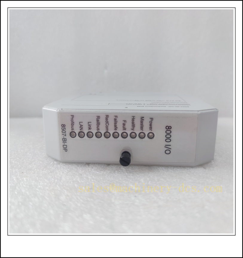
MTL8507-BI-DP
Technical Specifications
| Item | Parameter |
|---|---|
| Part Number | MTL8507-BI-DP |
| Product Type | PROFIBUS-DP Bus Interface Module (BIM) |
| System Platform | Eaton MTL PAC8000 |
| Communication Protocol | PROFIBUS-DP V0 / V1 (EN50170) |
| Supported Baud Rates | 9.6k,19.2k,93.75k,187.5k,500k,1.5M,6M,12 Mbaud (max) |
| Max Local I/O Modules | 24 pcs PAC8000 I/O modules per BIM |
| Power Supply | 24 VDC nominal |
| Isolation | Galvanic isolation between DP bus and I/O backplane |
| Special Feature | HART pass-through, extended DP diagnostics, non-volatile config memory |
| Operating Temperature | -40℃ ~ +70℃ |
| Storage Temperature | -40℃ ~ +85℃ |
| Mounting | DIN 35mm rail / flat panel mounting |
| Dimension | 178 ×170 ×68 mm |
| Weight | Approx. 0.45 kg |
| Start-up Time | ~15s (Firmware ≥1.23, Bootcode ≥2.00) |
| Configuration Method | Configured via PROFIBUS master with GSD file |
Compatibility & Installation Pitfalls
Compatibility
- Rack & Carrier: I/O rack; redundant pair requires 8701-CA-BI Redundant BIM Carrier
- I/O Modules: series DI, DO, AI, AO, pulse & HART I/O modules. Note: Older firmware versions have compatibility limitation with 8123-PI-QU /8223-PI-IS pulse input modules; upgrade firmware for full support
- Host System: Any PROFIBUS-DP master (PLC/DCS) supporting DP V0/V1
- Configuration Tool: Only configured by GSD file via PROFIBUS master; standalone I/O software cannot configure this BIM
Critical Installation Pitfalls
- GSD & firmware mismatch: Must use matching GSD file. Firmware incompatibility leads to I/O data loss or module fault; invalid firmware download triggers 60s fault blink then locks into upgrade mode.
- Redundancy carrier requirement: Dual redundant BIM cannot run on standard carrier; 8701-CA-BI dedicated redundant carrier is mandatory.
- PROFIBUS termination error: Both bus segment ends must install 120Ω DP terminator. Missing or duplicate termination causes unstable communication, random dropouts especially at high baud rate (≥1.5M).
- Ground loop risk: PROFIBUS cable shield single-end grounding; do not connect both ends to different ground potentials, which creates ground current and noise interference.
- Backplane connector damage: Hot insertion/removal with rack powered may bend backplane pins and permanently damage carrier or BIM.
- Address setting conflict: Rotate DIP switch for unique PROFIBUS slave address before power-on; duplicate slave address crashes DP segment.
- HART pass-through limitation: HART tunneling shares DP bandwidth; heavy HART background traffic may increase DP cyclic data latency.
Standard Operating Procedure (SOP)
1. Pre-Installation Inspection
- Verify part number MTL8507-BI-DP, inspect housing, pins and connectors for physical damage.
- Lockout/Tagout rack power, check carrier and backplane integrity.
- Prepare PROFIBUS GSD file, ESD protection, DP shielded cable, 120Ω terminator.
- Confirm firmware revision matches project I/O module list.
2. Mechanical Mounting
- Mount carrier on DIN 35mm rail. Insert BIM module and fasten captive retaining screws.
- For redundant system: Install two MTL8507-BI-DP onto 8701-CA-BI redundant carrier.
- Reserve side clearance for convection cooling.
3. Wiring & Address Setup
- Set PROFIBUS slave address via module DIP switches before energizing.
- Wire PROFIBUS DP bus using 135–165Ω PROFIBUS shielded cable, fit terminator at segment endpoints.
- Route DP cable separately from high-power cables. Terminate shield following single-side grounding rule.
- Plug I/O modules to the local backplane rack.
4. Power-Up & Commissioning
- Apply 24VDC supply, wait ~15s for module boot. Check front panel Power, Run, Fault LED indicators.
- Import MTL8507-BI-DP GSD file into PROFIBUS master project. Map I/O address list.
- Download project to DP master, establish cyclic communication.
- Verify extended diagnostics, check each I/O channel status.
- Test HART pass-through function if HART transmitters are deployed.
- Perform redundancy switchover test if redundant carrier configuration is applied.
5. Maintenance & Replacement
- Periodically inspect LED status, cable tightness, dust accumulation and cabinet temperature.
- For replacement: Power off rack, wear ESD wristband, remove faulty BIM, insert new module with matching firmware, reset slave address and reload DP configuration.
- Retrieve fault diagnostic codes via PROFIBUS master for troubleshooting communication or I/O failure.
Application Scenarios
- Oil & gas, refinery, chemical plant hazardous area distributed I/O control ( intrinsically safe I/O rack)
- Petrochemical DCS system PROFIBUS-DP remote I/O island
- Power plant auxiliary process control with HART instrument integration
- Pharmaceutical process control, water & wastewater treatment plant
- Offshore platform and heavy industrial process automation with redundant I/O requirement
Supporting / Matching Components
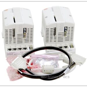
- 8701-CA-BI Redundant BIM Carrier (for dual BIM redundancy)
- series I/O modules (AI/AO/DI/DO/IS pulse modules)
- 24VDC redundant power supply for rack
- PROFIBUS-DP shielded cable (135~165Ω characteristic impedance)
- PROFIBUS 120Ω bus terminator
- ESD wrist strap and cabinet grounding bar
- backplane rack
- HART field transmitters (4-20mA HART)
- PROFIBUS-DP Master PLC / DCS controller
- MTL system documentation & GSD library
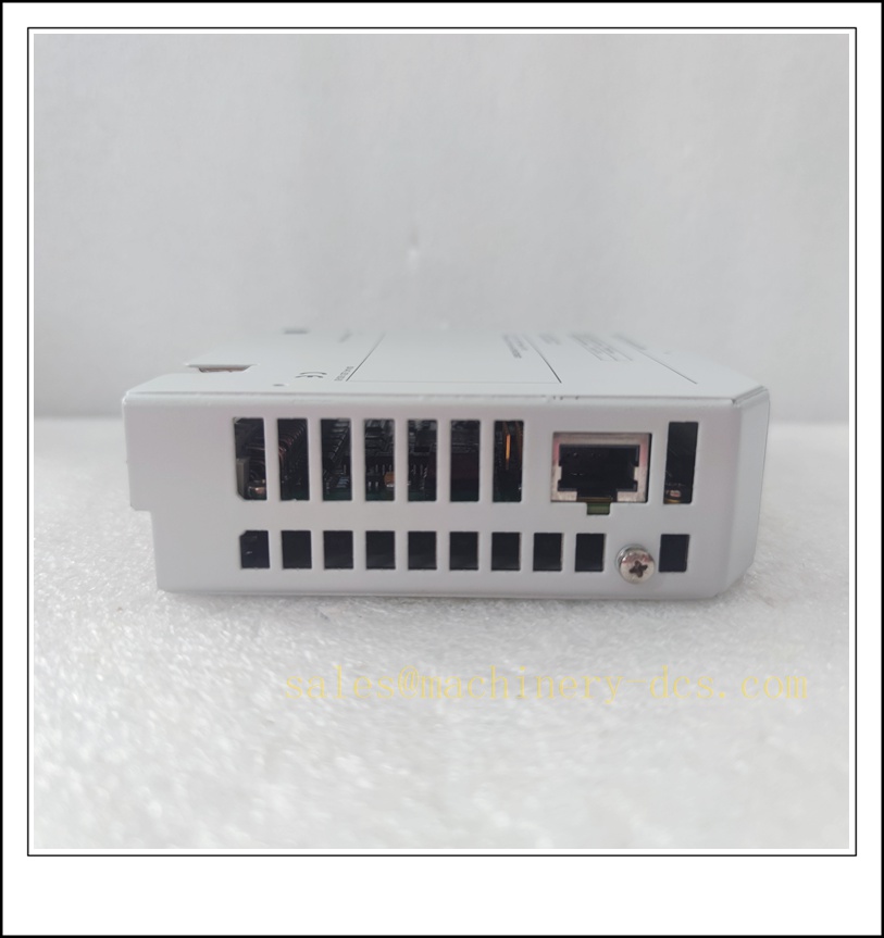
MTL8507-BI-DP
15 Recommended Same-Series / Compatible Models ()
- MTL8507-BI-BP – BIM alternative bus interface variant
- MTL8505-BI-MB – Modbus Bus Interface Module
- MTL8502-BI-DP-01 – Older generation PROFIBUS DP BIM
- 8109-DI-DC – Digital Input Module
- 8110-DI-DC – 24V DC DI Module
- 8220-DI-IS – Intrinsically Safe Digital Input
- 8204-AO-IS – Intrinsically Safe Analog Output
- 8205-TI-IS – Intrinsically Safe Temperature Input
- 8123-PI-QU – Pulse Input Module (require new BIM firmware)
- 8223-PI-IS – IS Pulse Input Module
- 8724-CA-PS – Rack Power Supply Carrier
- MTL8521-RT-DE – Ethernet/RT bus interface
- 8001-CC-35 – rack cable connector
- 8002-CC-85 – extension backplane cable
- 8111-DI-AC – AC Digital Input Module
FAQ
- Q: Can run standalone without I/O rack? A: No, it only works as backplane interface for I/O modules.
- Q: Can I configure this BIM directly via local software? A: No, configuration must be completed from PROFIBUS master using GSD file.
- Q: Does it support hot swap? A: Module hot-swap is not recommended under powered rack; power down before removal to protect backplane connector.

 Send an Email